Table of Contents
Advertisement
Quick Links
Advertisement
Table of Contents

Subscribe to Our Youtube Channel
Related Manuals for Wenglor P1NH Series


Summary of Contents for Wenglor P1NH Series
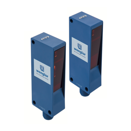
- Page 1 P1NHxxx Reflex Sensors with Background Suppression High-End with Teach-in Operating Instructions Translation of the Original Operating Instruction Subject to change without notice Available as PDF version only Version: 1.3.0 Status: 07.07.2020 www.wenglor.com...
-
Page 2: Table Of Contents
Table of Contents 1. General ...........................3 1.1 Information Concerning these Instructions ..................... 3 1.2 Explanations of Symbols ......................... 3 1.3 Limitation of Liability ..........................4 1.4 Copyrights ..............................4 2. For Your Safety ........................5 2.1 Use for Intended Purpose ........................5 2.2 Use for Other than the Intended Purpose .................... -
Page 3: General
• The product is subject to further technical development, and thus the information contained in these operating instructions may also be subject to change. The current version can be found at www.wenglor.com in the product’s separate download area. NOTE! The operating instructions must be read carefully before using the product and must be kept on hand for later reference. -
Page 4: Limitation Of Liability
• wenglor assumes no liability for printing errors or other inaccuracies contained in these operating instructions, unless wenglor was verifiably aware of such errors at the point in time at which the operating instructions were prepared. -
Page 5: For Your Safety
• The product is not suitable for use in potentially explosive atmospheres. • The product may only be used with accessories supplied or approved by wenglor, or combined with ap- proved products. A list of approved accessories and combination products can be accessed at www.wenglor.com on the product detail page. -
Page 6: Personnel Qualifications
• In the event of possible changes, the respectively current version of the operating instructions can be accessed at www.wenglor.com in the product’s download area. • Read the operating instructions carefully before using the product. -
Page 7: Technical Data
3. Technical Data Optical Data Service life (ambient temp. = +25 °C) 100000 h Max. permissible ambient light 10000 Lux Electrical Data Supply voltage 15…30 V DC IO-Link supply voltage 18…30 V DC Switching output voltage drop < 2 V Switching output switching current 100 mA Switching output residual current... -
Page 8: Spot Diameter
3.1 Spot Diameter Range 60 mm 250 mm 500 mm Spot diameter 11 mm 13 mm 15 mm Table 1 Range 160 mm 400 mm 800 mm Spot diameter 16 mm 20 mm 23 mm Table 2 Range 65 mm 150 mm 300 mm Spot diameter... -
Page 9: Switching Distance Deviation
3.2.1 Switching Distance Deviation Typical characteristic curve based on Kodak white (90 % remission). P1NH305, P1NH308 P1NH502, P1NH504 P1NH P1NH 100 150 200 250 300 350 Sr/mm Sr/mm P1NH702, P1NH704 P1NH Sr/mm Sr = Switching Distance dSr = Switching Distance Change Black 6 % remission Grey 18 % remission Reflex Sensors with Background Suppression High-End with Teach-in... -
Page 10: Complementary Products
3.3 Complementary Products wenglor can provide you with suitable connection technology for your product. Suitable mounting technology no. Suitable connection technology IO-Link master wTeach2 software DNNF005 Protection Housing Set Z1NS001 STAUBTUBUS-03 3.4 Layout P1NH305, P1NH308 Technical Data... - Page 11 P1NH502, P1NH504 P1NH702, P1NH704 = Emitter diode = Receiving diode Screw M4 = 0,5 Nm Dimensions specified in mm (1 mm = 0,03937 Inch) Reflex Sensors with Background Suppression High-End with Teach-in...
-
Page 12: Control Panel
3.5 Control Panel A 31 5a 68 6a 2a = NFC interface 5a = switching distance adjuster A1 6a = switching distance adjuster A2 06 = Teach Button 68 = supply power indicator 3.6 Scope of Delivery • Sensor • Safety precautions •... -
Page 13: Transport And Storage
4. Transport and Storage 4.1 Transport Upon receipt of shipment, the goods must be inspected for damage in transit. In the case of damage, con- ditionally accept the package and notify the manufacturer of the damage. Then return the device, making reference to damage in transit. -
Page 14: Electrical Connection
5.2 Electrical Connection Legend Encoder A/A (TTL) Platinum measuring resistor Encoder B/B (TTL) Supply Voltage + not connected Encoder A Supply Voltage 0 V Test Input Encoder B Supply Voltage (AC Voltage) Test Input inverted Digital output MIN Switching Output (NO) Trigger Input Digital output MAX... -
Page 15: Diagnostics
5.3 Diagnostics Causes for Triggering the Contamination Warning (blinking LED): Display LED Diagnosis/Cause Elimination Contamination Carefully clean the optic cover with a cloth. Continuous blinking Aged emitter diode Replace the sensor. at approx. 2.5 Hz • Increase the sensor’s switching distance. Unreliable working range •... -
Page 16: Settings
6. Settings The switching distance to the object can be taught in for both outputs by pressing the teach-in key on the sensor (default setting is foreground teach-in). Teach-In for Switching Output 1 1. Mount the sensor in accordance with the mounting instructions. 2. -
Page 17: Background Teach-In
7.1.2 Background Teach-In Teach-In is performed while the sensor spot is aligned to the background. The switching distance is then au- tomatically set to a distance which is slightly less than the clearance between the sensor and the background. The sensor is thus activated whenever an object is located between the background and the sensor. Sensor Teach-in distance Object... -
Page 18: Error Output
• On/off-delay • Operating mode • Switch emitted light off • Test mode • Data storage (IO-Link) 8. IO-Link Process and parameters data, as well as the IODD, can be found at www.wenglor.com in the product’s sepa- rate download area. IO-Link... -
Page 19: Nfc
Android smartphone and wenglor’s “Sensor Configurator” app. Process data cannot be read out via NFC but they’re available via IO-Link. The wenglor app can be downloaded free of charge from the Google Play Store. Download the app and follow the installation instructions. -
Page 20: Proper Disposal
“3 Technical Data” on page 7 ff 1.3.0 07.07.20 Updates of “3 Technical Data” on page 7 ff 12.3 EU Declaration of Conformity The EU declaration of conformity can be found on our website at www.wenglor.com in the product’s download area. Proper Disposal...
Need help?
Do you have a question about the P1NH Series and is the answer not in the manual?
Questions and answers