Subscribe to Our Youtube Channel
Summary of Contents for Dahua 59430IC
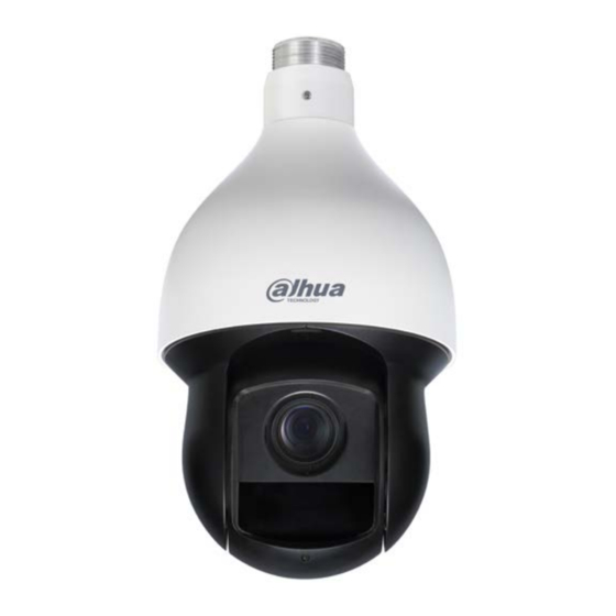
- Page 1 4 MP HDCVI PTZ Network Camera 59430IC/59230IC Quick Start Guide Version 001.001 Dahua Technology USA Inc.
-
Page 2: Table Of Contents
Table of Contents Welcome........................1 Important Safeguards and Warnings ..............1 Electrical safety ....................1 Environmental Precautions ................2 Operation and Daily Maintenance ..............3 Lifting Appliance Requirement ................3 Warnings ......................3 FCC Information ....................4 FCC compliance: .................... 4 Legal Notices .................... -
Page 3: Welcome
This manual offers reference material and general information about the basic operation, maintenance, and troubleshooting of the Dahua Multi-Sensor Panoramic Camera. Read, follow, and retain the following safety instructions. Heed all warning on the unit and in the operating instructions before operating the unit. -
Page 4: Environmental Precautions
Ensure a service technician uses replacement parts specified by the manufacturer, or that have the same characteristics as the original parts. Unauthorized parts may cause fire, electrical shock, or other hazards. Dahua is not liable for any damage or harm caused by unauthorized modifications or repairs. -
Page 5: Operation And Daily Maintenance
• Dahua recommends the use of a thunder-proof device in concert with the unit. • Do not touch the CCD or the CMOS optic sensor. Use a blower to clean dust or dirt on the lens surface. -
Page 6: Fcc Information
1.3 Legal Notices Copyright This user guide is ©2017, Dahua Technology Company, LTD. This user guide is the intellectual property of Dahua Technology Company, LTD and is protected by copyright. All rights reserved. Trademarks All hardware and software product names used in this document are likely to be registered... -
Page 7: Disclaimer
• Video loss is inherent to all digital surveillance and recording devices; therefore Dahua cannot be held liable for any damage that results from missing video information. To minimize the occurrence of lost digital information, Dahua recommends multiple, redundant recording systems, and adoption of backup procedure for all data. -
Page 8: Unpacking
2 Unpacking This equipment should be unpacked and handled with care. If an item appears to have sustained damage during shipping, notify the shipper immediately. Verify that all the parts listed below are included. If an item is missing, contact customer support or your local representative. -
Page 9: Installation And Configuration
3 Installation and Configuration 3.1 Framework and Dimensions The following figures show the dimensions of the device in mm (in.). These images are intended as a reference only. Figure 3-1: Dimensions for 59430IC... -
Page 10: Wiring
3.2 Wiring The dome camera includes the following wiring bundles: Wire Color Connection Power 24 VAC Yellow/Green Earth Ground Black 24 VAC Alarm Alarm IN 1 Brown Alarm IN 2 Yellow/Green Alarm GND Blue Alarm OUT 1 Green Alarm COM 1 Video Pink Video Out... -
Page 11: Alarm Output - Level Application
Alarm Output – Level Application Use this alarm output configuration if the output triggers an external device by increasing the voltage. The alarm must increase the external pull-up resistance to trigger (high level) the device. The maximum external pull-up level is 5 V and the maximum port current is 5 mA. Once the output increases the pull-up resistance, the alarm decreases the output voltage to the normal state (low level) at less than 0.8 V. -
Page 12: Device Installation
A readily accessible 2-pole disconnect device with a contact separation of at least 3 mm must be incorporated. Note: Dahua recommends attaching a “drip loop” (flex or hard conduit) during installation to ensure condensation does not form in the mount or the conduit. -
Page 13: Cable Requirements
The hardware must be capable of supporting eight (8) times the weight of the camera and mount. • Appropriate tools to mount the camera to the wall. Transmission distance results verified by real-scene testing in Dahua's test laboratory. Actual transmission distances may vary due to external influences, cable quality, and wiring structures. -
Page 14: Unpacking The Camera
Unpacking the Camera 1. Remove the camera, the mount accessories and any hardware packages from the boxes. 2. Remove the camera from the plastic wrapping and place the camera dome-end up in the foam packaging. 3. Remove the protective tape from the dome. Protective Tape 4.3 Mounting the Camera to a Wall 1. - Page 15 7. Place the PFB300S Wall Mount against the wall and mark the location of the center hole and the four perimeter mounting holes. 8. Pull the composite cable from the dome through the adapter block and pull it out of the other end of the wall mount bracket.
- Page 16 Dahua Technology USA Inc. 23 Hubble, Irvine, CA 92618 Tel: (949) 679-7777 Fax: (949) 679-5760 Email: sales.usa@global.dahuatech.com Rev 001.001 © 2017 Dahua. All rights reserved. Design and specifications are subject to change without notice.


Need help?
Do you have a question about the 59430IC and is the answer not in the manual?
Questions and answers