
Subscribe to Our Youtube Channel
Related Manuals for Mitsubishi Melsec FX-2DA


Summary of Contents for Mitsubishi Melsec FX-2DA
- Page 1 (217) 352-9330 | Click HERE Find the Mitsubishi FX-48MR-ES/UL at our website:...
- Page 2 FX-2DA SPECIAL FUNCTION BLOCK USER'S GUIDE JY992D52801C This manual contains text, diagrams and explanations which will guide the reader in the correct installation and operation of the FX-2DA special function block and should be read and understood before attempting to install or use the unit. Further information can be found in the FX PROGRAMMING MANUAL and FX SERIES HARDWARE MANUAL.
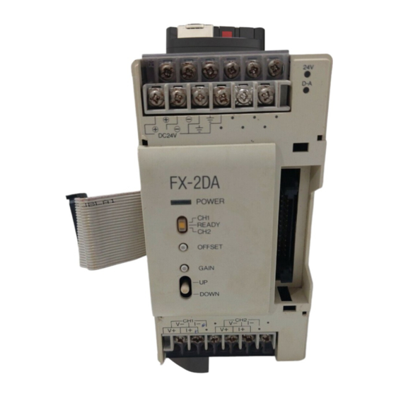
- Page 3 1.1 External dimensions Weight : Approx. 0.5kg (1.1 lbs) Dimensions : mm (inches) 24V LED Extension cable D-A LED and connector Any connection to these terminals Groove for may damage the FX-2DA. 35mm (1.38) wide DIN rail 2-5.5mm (0.22) hole M3.5 (0.14) terminal screws 63 (2.48)
-
Page 4: Installation Notes And Usage
INSTALLATION NOTES AND USAGE 3.1 Environment specification Item Specification Environment specifications Same as those for the FX base unit 3.2 Power supply specifications Specification Item 24V DC ±10% 130mA Analog circuits (external power supply) 5V DC, 30mA Digital circuits (internal power supply from base unit) 3.3 Performance specifications Voltage output Current output... - Page 5 Miscellaneous Item Specification Photo-coupler isolation between analog and digital circuits. DC/DC converter isolation of power from FX base unit. Isolation No isolation between analog channels. Number of occupied I/O 8 points taken from the FX expansion bus points (can be either inputs or outputs) ATTENTION FOR WHEN SWITCHING SYSTEM ON/OFF Due to the inevitable timing difference of the DC24V for the analog circuits and other power lines of the base unit, the output of the FX-2DA special function block may behave erroneously before settling down...
- Page 6 3.4 Allocation of buffer memories (BFM) In BFM's (buffer memory) with an “ * ”, data contents can be written from the programmable cont- *# 0 channel Initialization (Default = H00) roller using the TO command. *# 1 channel 1 *# 2 channel 2 # 3-# 4...
- Page 7 (1) Channel Selection Switching between voltage and current output modes. The value of BFM #0 switches the analog output between voltage and current on channels CH1 and CH2. It takes the form of a 2-character HEX number. The least significant character controls CH1 and the other controls CH2. Control of each O HEX character of O=0 Voltage output (-10V to +10V) O=1 Current output (+4mA to +20mA)
- Page 8 (5) Status information BFM #29 When any of b1 to b3 is ON D/A conversion b 0 : error No error is stopped for the error channel Offset/Gain data in EEPROM is corrupted or b 1 : Offset/Gain error Offset/Gain data normal adjustment error b 2 : Power abnormality DC 24V power supply failure...
- Page 9 DEFINING GAIN AND OFFSET 〈 〈 〈 〈 〈 GAIN〉 〉 〉 〉 〉 〈 〈 〈 〈 〈 OFFSET〉 〉 〉 〉 〉 Analog Analog Digital value 0 Gain value 1000 Digital Digital Offset value Gain is the angle or slope of the calibration line Offset is the 'Potion' of the calibrated line, identified identified at a digital value of 1000.
-
Page 10: Example Program
EXAMPLE PROGRAM 5.1 Basic program In the following example, channel CH1 is set to voltage output, while CH2 is set to current output. The FX- 2DA unit is connected at the position of special function block No.1. If the programmable controller is changed to the STOP mode, the last data sent will remain and the outputs will hold. - Page 11 5.2 Using gain and offset in a program I/O characteristics of the FX-2DA can be adjusted by changing the gain and offset parameters. These can be changed by the switches of the FX-2DA with the aid of Voltage & Current meters or simply changed by writting these settings from the programmable controller.
- Page 12 DIAGNOSTICS 6.1 Preliminary checks 1. Check whether the output wiring and/or expansion cables are properly connected on FX-2DA analog special function block. 2. Check that the FX system configuration rules have not been broken, i.e. the number of blocks does not exceed 8 and the total system I/O is equal or less than 256 I/O.
- Page 13 If in doubt about the operation or use of the FX-2DA please consult the nearest Mitsubishi Electric distributor. Under no circumstances will Mitsubishi Electric be liable or responsible for any consequential damage that may arise as a result of the installation or use of this equipment.
Need help?
Do you have a question about the Melsec FX-2DA and is the answer not in the manual?
Questions and answers