Frymaster H50 Series Service And Parts Manual
Hide thumbs
Also See for H50 Series:
- Service and parts manual (138 pages) ,
- 819-5463 24-std. service-hotline 1-800-551-8633 aug 2002 installations- und gebrauchsanleitung (52 pages) ,
- Service and parts manual (96 pages)

Subscribe to Our Youtube Channel
Related Manuals for Frymaster H50 Series


Summary of Contents for Frymaster H50 Series
- Page 1 Frymaster, a member of the Commercial Food Equipment Service Association, recommends using CFESA Certified Technicians. 24-Hour Service Hotline 1-800-551-8633 JUNE 2007 *8190001*...
- Page 2 DIRECTLY FROM FRYMASTER/DEAN, OR ANY OF ITS AUTHORIZED SERVICE CENTERS, AND/OR THE PART BEING USED IS MODIFIED FROM ITS ORIGINAL CONFIGURATION, THIS WARRANTY WILL BE VOID. FURTHER, FRYMASTER/DEAN AND ITS AFFILIATES WILL NOT BE LIABLE FOR ANY CLAIMS, DAMAGES OR EXPENSES INCURRED BY THE CUSTOMER WHICH ARISE DIRECTLY OR INDIRECTLY, IN WHOLE OR IN PART, DUE TO THE INSTALLATION OF ANY MODIFIED PART AND/OR PART RECEIVED FROM AN UNAUTHORIZED SERVICE CENTER.
- Page 3 DANGER No structural material on the fryer should be altered or removed to accommodate placement of the fryer under a hood. Questions? Call the Frymaster/Dean Service Hotline at 1-800-551-8633. DANGER Adequate means must be provided to limit the movement of this appliance without depending upon the gas line connection.
-
Page 4: Table Of Contents
H50 SERIES GAS FRYERS TABLE OF CONTENTS CHAPTER 1: Service Procedures Functional Description.......................1-1 The Electronic Ignition System ..................1-1 Interface Boards .........................1-2 Thermostats........................1-4 Accessing Fryers for Servicing..................1-4 Cleaning the Gas Valve Vent Tube ...................1-4 Checking the Burner Manifold Gas Pressure..............1-5 Measuring Flame Current ....................1-7 Replacing Fryer Components ....................1-7... - Page 5 H50 SERIES GAS FRYERS TABLE OF CONTENTS CHAPTER 2: Parts List Accessories........................2-1 Basket Lift Assemblies and Component Parts ..............2-2 2.2.1 Bell Crank Basket Lifts ..................2-2 2.2.2 Modular Basket Lifts..................2-4 Blower Assemblies and Associated Components ............. 2-6 Casters, Legs, and Restraints.....................
-
Page 6: Chapter 1: Service Procedures
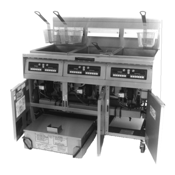
H50 SERIES GAS FRYERS CHAPTER 1: SERVICE PROCEDURES Functional Description H50 Series fryers contain a welded stainless steel frypot that is directly heated by a high efficiency infrared burner system requiring approximately 43% less energy than conventional burners to cook the same volume. -
Page 7: Interface Boards
The H50 Series of fryers has been in production since 1983. Consequently, servicers are likely to encounter three different interface board designs. Although the boards differ slightly in appearance, basic functioning and electrical connections are the same from one to another. - Page 8 ** See Probe Resistance Chart at end of chapter. *** 5 mega-Ohms or greater. These standard interface boards are also used in a number of fryer types besides the H50 Series. The information contained in this section applies to H50 Series applications ONLY.
-
Page 9: Thermostats
(setpoints). The temperatures are programmed by means of a keypad on the face of the controller. H50 Series fryers are also equipped with a high-limit thermostat. In the event that the fryer fails to properly control the oil temperature, the high-limit thermostat prevents the fryer from overheating to the flash point. -
Page 10: Checking The Burner Manifold Gas Pressure
Checking the Burner Manifold Gas Pressure 1. On non-CE fryers, ensure that the gas valve knob is in the OFF position. Honeywell 2. Remove the pressure tap plug from the gas valve assembly. Pressure Tap Plug Typical Non-CE Typical CE Valve Valve Assembly Assembly 2. - Page 11 CE Standard CE Standard Burner Manifold Gas Pressures Burner Manifold Gas Pressures for Fryers Manufactured After April 1999 for Fryers Manufactured Through April 1999 Pressure (mbar) Pressure (mbar) Single Dual Single Dual Natural Gas Lacq Natural Gas Lacq (G20) under 20 mbar (G20) under 20 mbar Natural Gas Gronique * Natural Gas Gronigue *...
-
Page 12: Measuring Flame Current
Measuring Flame Current When the burner flame is properly adjusted, it will produce a current between 2.5 μA and 3.5 μA. Flame current is measured by placing a microamp (not milliamp) meter in series with the sensing wire on the ignitor. This is accomplished as follows: 1. -
Page 13: Replacing The Interface Board
7. Disconnect the ignition cables from the ignitors by grasping the boots and gently pulling toward you. 8. Remove the component box mounting screws. 9. Rotate the top of the component box out of the frame and carefully pull it out enough to disconnect the wiring harness plug(s) from the back of the box. -
Page 14: Replacing An Ignitor Assembly
5. Reverse the procedure to install the replacement module. 1.6.5 Replacing an Ignitor Assembly DANGER Drain the frypot or remove the handle from the drain valve before proceeding further. 1. Disconnect the fryer from the electrical supply. 2. Disconnect the ignition cable from the ignitor by grasping the boot and gently pulling toward you. - Page 15 Remove these fasteners. (On black-colored FASCO blowers there are three nuts. On silver-colored KOOLTRONICS blowers there are three screws.) 3. Wrap the motor with plastic wrap to prevent water from entering it. Spray degreaser or detergent on the blower wheel and the blower housing. Allow it to soak for five minutes. Rinse the wheel and housing with hot tap water, then dry with a clean cloth.
- Page 16 Left Viewing Port is Behind Motor Right (NOTE: Blower Viewing shield omitted Port for clarity.) The air/gas mixture is properly adjusted when the burner manifold pressure is in accordance with the applicable table on page 1-6 and the burners display a bright orange-red glow. If a blue flame is observed, or if there are dark spots on a burner face, the air/gas mixture requires adjustment.
-
Page 17: Replacing A Gas Valve
Adjusting Air/Gas Mixture CE Units Built Through April 1999 CE units built through April 1999 are equipped with a shield assembly in front of the blowers. An air shutter plate on the face of the shield assembly regulates the amount of airflow to the blower in- take. -
Page 18: Replacing A Burner Assembly
1.6.8 Replacing a Burner Assembly DANGER Drain the frypot or remove the handle from the drain valve before proceeding further. 1. Disconnect the unit from the electrical and gas supplies. 2. Remove the combustion air blower per the procedure found in Section 1.6.6. 3. -
Page 19: Replacing The Frypot
15. Examine the burner flame. The color and intensity on both sides should be the same. 16. Use an inspection mirror to check for leaks in areas that cannot be directly observed. 17. If a leak is detected, tighten all the lower insulation retainer nuts, allow the frypot to run for five additional minutes, and repeat steps 15 and 16. -
Page 20: Replacing Frypot Insulation And/Or Upper Burner Rails
16. Carefully lift the frypot from the fryer cabinet. 17. Remove the drain valve(s), temperature probe(s), high-limit thermostat(s), and ignitor assemblies. Inspect each of these components carefully and install them in the replacement ® frypot if they are in serviceable condition. Use Loctite PST56765 sealant or equivalent on component threads. - Page 21 10. Remove the flue assembly (10). 11. Remove the upper burner rails (11). NOTE: For the following steps, refer to the frypot exploded view on page 3-19 for component iden- tification. 12. Remove any residual insulation, sealant, and/or oil from the exterior of the frypot. 13.
- Page 22 1-17...
- Page 23 1-18...
- Page 24 21. Insert the burners (9) into the rails to ensure the rail spacing and alignment are correct. The burner should slide freely into and out of the rails. The upper rail can be bent slightly to increase or decrease tension on the burner, and the edges of the slot can be closed or opened slightly to best fit the burner frame.
-
Page 25: Troubleshooting And Problem Isolation
33. Install the upper oil-zone insulation (21) by pressing it under the upper combustion chamber metalwork. Secure the insulation with the bracket (22) and ¼” self-tapping screws. 34. Install the upper burner rail blanket insulation (23). Position any excess insulation toward the top of the frypot. - Page 26 PROBLEMS RELATED TO THE GAS AND/OR ELECTRICAL POWER SUPPLIES The main indicators of this are that an entire battery of fryers fails to light and/or there are no indicator lights illuminated on the fryer experiencing ignition failure. Verify that the quick disconnect fitting is properly connected, the fryer is plugged in, the main gas supply valve is open, and the circuit breaker for the fryer electrical supply is not tripped.
- Page 27 If popping occurs only during peak operating hours, the problem may be incorrect or fluctuating gas pressure. Verify that the incoming gas pressure (pressure to the gas valve) is in accordance with the appropriate table below, and that the pressure remains constant throughout all hours of usage. Refer to Check Burner Manifold Pressure in the section of 1.4 for the procedure for checking the pressure of gas supplied to the burner.
- Page 28 If all other causes have been ruled out, examine the burner tiles for any signs of cracking. If cracks are found, the burner must be replaced. Fluctuating flame intensity is normally caused by either improper or fluctuating incoming gas pressure, but may also be the result of variations in the kitchen atmosphere.
- Page 29 325ºF (163ºC) point by pressing button and entering the code 1652. The test results will be displayed in the computer’s LED panel in minutes and seconds. The maximum acceptable recovery time for the H50 Series of fryers is two minutes and twenty-five seconds.
-
Page 30: Filtration Problems
1.7.5 Filtration Problems The majority of filtration problems arise from operator error. One of the most common errors is placing the filter paper on the bottom of the filter pan rather than over the filter screen. Whenever the complaint is “the pump is running, but no oil is being filtered,” check the installation of the filter paper, including that the correct size is being used. - Page 31 Pan blockage can also occur if shortening is left in the pan and allowed to solidify. The heater strip on the suction tube is designed to prevent solidification of residual shortening left in the tube. It will not melt or prevent solidification of shortening in the pan. Blockage removal can be accomplished by forcing the item out with an auger or drain snake.
- Page 32 For a short time, one-piece, welded oil return manifolds were used. The one-piece manifolds have been replaced with Dormont stainless steel flexlines and nipples and are no longer available. PRE-AUGUST 1997 VS CURRENT DESIGN FP-III FILTRATION SYSTEM Original System Redesigned System Return lines and manifolds wrapped with silicone No heater strips or aluminum tape on return strip heaters and aluminum tape.
-
Page 33: Leakage
1.7.7 Basket Lift Malfunctions H50 Series fryers may optionally be equipped with automatic basket lifts to ensure uniform cooking times. Basket lifts will always come in pairs, although each operates independently of the other. - Page 34 100/120V Modular Basket Lift Assembly 806-8530SP (TYPICAL) 1-29...
- Page 35 A bell crank style basket lift consists of a cam and bell crank that are connected to the basket lift arm by a flat metal link. The cam is attached to a drive motor. The motor ro- tates the cam, thus raising or lowering the lift arm linked to the bell crank.
-
Page 36: Interpretation Of Digital Controller Lights
An additional set of operator troubleshooting guides is contained in Chapter 6 of the H50 Series Installation and Operation Manual (P/N 819-5000). It is suggested that service technicians thoroughly familiarize themselves with both sets. - Page 37 PROBLEM PROBABLE CAUSES CORRECTIVE ACTION A. Failed 24V transformer. A. If the wiring and connections be- tween the 24V transformer and Check: LED 3 (24V) is not lit the interface board are intact, re- continuously. place the transformer. B. Failed interface board. Check 1: LED 3 (24V) is lit continuously, but 24 VAC is not present on the right PWR terminal...
- Page 38 24 VOLT CIRCUIT With Interface Board 806-3398 or 106-0386 807-1006 (FV/DV), 807-2971 (FV/DV), or 807-3365 (DV) Ignition Modules TRANSFORMER LED 3 (24V) J1 PIN 8 J3 PIN 8 Heat Relay Heat Relay (K1 Fixed) (K2 Fixed) (K2 Replaceable) (K3 Replaceable) 2 (PWR) LED 4 (PWR) FV = Full Vat...
- Page 39 24 VOLT CIRCUIT With Interface Board 806-3398 or 106-0386 807-3366 (FV) Ignition Module TRANSFORMER LED 3 (24V) J3 PIN 8 NOTE: Some units may be wired in this manner. Heat Relay (K2 Fixed) (K3 Replaceable) IGNITION LED 4 (PWR) MODULE PWR (right side) Left Flame High Voltage...
-
Page 40: Probe Resistance Chart
Resistance Chart for the corresponding temperature. Check 2: Check least megaohms of resistance through each of the previously tested pins to ground. Probe Resistance Chart For use with H50 Series fryers manufactured with Minco Thermistor probes only. OHMS OHMS OHMS OHMS OHMS 1059 1204... -
Page 41: Simplified Wiring Diagrams
Simplified Wiring Diagrams 1-36... - Page 42 1-37...
- Page 43 1-38...
- Page 44 1-39...
- Page 45 1-40...
-
Page 46: Principal Wiring Connections
1.10 Principal Wiring Connections N.C. LINE VOLTAGE C2 PIN 1 AIR SWITCH (L1) N.O. (CE AND SOME LINE VOLTAGE (COM) C2 PINS 3 & 12 EXPORT UNITS) (IN COMPONENT BOX) LINE VOLTAGE (L1) BLACK TO T1 & J3 PIN 11 GROUND GREEN TO GROUND... -
Page 47: Wiring Diagrams - Main
1.11 WIRING DIAGRAMS - MAIN FPH150 ONLY (NON-CE) 1-42... - Page 48 FPH150 ONLY (CE) 1-43...
- Page 49 H50 SERIES (NON-CE) OTHER THAN FPH150 AND MANUFACTURED GAS UNITS (Old Single Spark Ignition Module) ON SOME OLDER UNITS C4 HAD A 6-PIN PLUG 1-44...
- Page 50 H50 SERIES (NON-CE) OTHER THAN FPH150 AND MANUFACTURED GAS UNITS (Newer Dual-Spark Ignition Module) FULL VAT COMPUTER OR CONTROLLER TEMP TO J2 PROBE HIGH SOUND DEVICE LIMIT SOUND SENSE 2 SENSE 1 SAFETY DRAIN ALARM(GND) ALARM NO COM VALVE(GND) LEFT...
- Page 51 H50 SERIES (CE) OTHER THAN FPH150 AND MANUFACTURED GAS UNITS BLACK 1-46...
- Page 52 H50 SERIES MANUFACTURED GAS UNITS 1-47...
-
Page 53: Wiring Diagrams - Transformer Boxes
1.12 WIRING DIAGRAMS – TRANSFORMER BOXES Non-CE Transformer Boxes 1-48... - Page 54 CE Transformer Boxes 1-49...
-
Page 55: Wiring Diagrams - Basket Lifts
1.13 WIRING DIAGRAMS – BASKET LIFTS Modular Basket Lift – 100/120V (NOTE: There is no CE version of this option.) RIGHT SIDE LEFT SIDE 101C RESISTOR RED 2 BRN 1 RED 1 BRN 2 12.5 12.5 UPPER UPPER SWITCH SWITCH LOWER LOWER SWITCH... - Page 56 Modular Basket Lift – 208/250V (NOTE: This diagram is used for both CE and Non-CE applications.) RIGHT SIDE LEFT SIDE (NOT USED ON 208/220V) 25ohm 25ohm RED 2 BRN 1 RED 1 BRN 2 101C 12.5 12.5 100ohm 100ohm 100C UPPER UPPER SWITCH...
- Page 57 Bell Crank Basket Lift ( NOTE: There is no CE version of this option.) 1-52...
-
Page 58: Wiring Diagrams - Filter Boxes
1.14 WIRING DIAGRAMS – FILTER BOXES FootPrint III Prior to August 1997 (NOTE: This diagram is used for both CE & Non-CE applications.) TO FRYER 7 8 9 4 5 6 1 2 3 PUMP RELAY BLACK TO PIN 4 PUMP HEATER WHITE... -
Page 59: Wiring Diagrams - Oil Return
Filter Magic II (NOTE: This diagram is used for both CE and Non-CE applications.) 29C WHT 7P WHT 11C BLK EXTERNAL 23C BLK 22C BLK POWER SOURCE LINE VOLTAGE 25C BLU TRANSFORMER RELAY LOAD 24VAC 27C ORG 21C ORG NON- DIRECT OPTION HEATER TAPE FROM PUMP LINE... - Page 60 Oil Return/Wand Wiring (Japan) Oil Return/Disposal Wand Wiring (Sonic) 1-55...
-
Page 61: Chapter 2: Parts List
H50 SERIES GAS FRYERS CHAPTER 2: PARTS LIST Accessories ITEM PART # COMPONENT 803-0271 Basket, Twin 803-0099 Basket, Full (cannot be used with basket lifts) 803-0133 Basket Support Rack, Dual Vat 803-0132 Basket Support Rack, Full Vat 803-0136 Basket Support Screen, Full Vat (screen w/handle used in place of Item 4) -
Page 62: Basket Lift Assemblies And Component Parts
Basket Lift Assemblies and Component Parts 2.2.1 Bell Crank Basket Lifts... - Page 63 ITEM PART # COMPONENT Gear Motor, Basket Lift 807-0107 120VAC 807-0108 240VAC 807-0124 Bushing, Plastic 807-0240 Microswitch 826-1680 Clamp, Plastic Wire (Pkg. of 8) 826-1358 Nut, 6-32 Hex (Pkg. of 25) 809-0050 Nut, 2-32 Hex Nut, Jam ⅜-16 Hex 809-0063 809-0076 Nut, ¼-20 x ¾...
-
Page 64: Modular Basket Lifts
2.2.2 Modular Basket Lifts... - Page 65 ITEM PART # COMPONENT Mount, Modular Basket Lift** 200-2942 For use on units with 12-pin connectors 900-7655 For use on units with 6-pin connectors 806-5964SP Motor Assembly, Modular Basket Lift 810-1013 Gear, Modular Basket Lift (809-0504 Set Screw, 6-32 x .185) Capacitor, 12.5 μFarad, 250VAC Motor Run 807-2513 807-2572...
-
Page 66: Blower Assemblies And Associated Components
Blower Assemblies and Associated Components ITEM PART # COMPONENT Blower, Left (with 1.54-inch (3.91 cm) narrow housing) 106-2996SP 100V, 50/60 Hz 106-2994SP 115V, 50/60 Hz 806-5841SP 230V, 50 Hz 106-2995SP 240V, 50 Hz Blower, Right (with 1.54-inch (3.91 cm) narrow housing) 806-4697SP 100V, 50/60 Hz 106-2997SP... -
Page 67: Casters, Legs, And Restraints
ITEM PART # COMPONENT 826-1383 Washer, ¼-inch Flat (for mounting blower to plenum) (Pkg. of 5) 826-1372 Nut, ¼-20 Hex (for mounting blowers to plenum) (Pkg. of 10) KIT-0155SP High Altitude Blower Kit (required above 5000 Ft, 1525 M) * Not illustrated. NOTES: Items 5, 6, and 7 are components of Items 3 and 4. -
Page 68: Burner Ignition System Components And Associated Hardware
Burner Ignition System Components and Associated Hardware ITEM PART # COMPONENT See Pg 2-7 Ignition Module, Full and Dual Vat (original design, with fuse) 807-0910 Fuse See Pg 2-7 Ignition Module, Full Vat (new design, without fuse) 826-1346 Spacer (Pkg. of 10) See Pg. -
Page 69: Component Box Assemblies And Associated Component Parts
Component Box Assemblies and Associated Component Parts 106-0386 (Item 7) has two IFB 806-3398 (Discontinued) has only one fuses and may be used with any fuse. If used with 807-3365 807-3366 of the ignition modules. modules, an in-line fuse should be added between the module and the board. -
Page 70: Controller Assemblies
Controller Assemblies SOLID STATE ITEM PART # COMPONENT Computer Magic III 106-1187SP Dual Vat (CE) 106-1151SP Dual Vat (Non-CE) 106-1155SP Dual Vat w/ 8 sec. Melt Cycle 106-1188SP Full Vat (CE) 106-1150SP Full Vat (Non-CE) 106-1216 Full Vat, Remote BK on the Hood 106-1226 Full Vat, Remote BK in the Hood Basket Lift Timer... -
Page 71: Drain Valves, Drain Valve Assemblies And Associated Parts
Controller Assemblies cont. ITEM PART# COMPONENT 826-1379 Screw, #10 X ½-inch Philips Truss Head (computer screws) (Pkg. of 10) 910-3690 Blank Panel (for fryers with remote mounted computers) 806-2071 Harness, Main Short Wire 14 ½” 15-pin Computer to Interface Board 806-3528 Harness, Main 7 ½’... - Page 72 2.8.2 MJH50 Drain Valve Assemblies Dual-Vat (1-inch) Assemblies 806-7915SP 806-7916SP ITEM PART # COMPONENT 806-7915SP Complete Assembly, Left 806-7916SP Complete Assembly, Right Components 810-1338 Drain Valve, 1-inch NPT Inlet and Outlet (See NOTE) Nut, 2-way Lock, ⅜–16 809-0539 810-1568 Handle, Drain Valve, w/Lock Pin, Left 810-1567 Handle, Drain Valve, w/Lock Pin, Right NOTE: For a short period in early 2003, some versions of these assemblies were manufactured with valves...
-
Page 73: Fmh50 Dual Vat (1-Inch) Drain Valve Assemblies
2.8.3 FMH50 Dual Vat (1-Inch) Valve Assemblies NOTES: Compression washers must be turned face to face and lock nut (Item 9) must be torqued to 60 ± 10 inch-pounds. Item 3 does not come with 806-7432SP 806-7433SP. Compression Washers Compression Washers (part of Item 1) (part of Item 1) Steel Flat Washer... -
Page 74: Fmh50 Full Vat (1¼-Inch) Drain Valve Assembly
2.8.4 FMH50 Full Vat (1¼-inch) Valve Assembly NOTES: Compression washers must Compression Washers be turned face to face and lock nut (part of Item 1) (Item 5) must be torqued to 80 ± 10 806-8791SP inch-pounds. Item 11 does not come with assembly 806-8791SP. -
Page 75: Fph50 Dual Vat (1-Inch X 1¼-Inch) Valve Assemblies
2.8.5 FPH50 Dual Vat (1-Inch X 1¼-inch) Valve Assemblies N O TE : C o m p r e s s i o n washers must be turned face to face and lock nut (Item 16) must be torqued to 60 ± 10 inch-pounds. Compression Washers (part of Item 4) -
Page 76: Fph50 Full Vat (1¼-Inch) Valve Assemblies
2.8.6 FPH50 Full Vat (1¼-inch) Valve Assemblies N O TE : Co m pre s s i on Compression Washers washers must be turned (part of Item 1) face to face and lock nut (Item 13) must be torqued to 80 ± 10 inch-pounds. Steel Flat Washer (part of Item 1) Plastic Washer... -
Page 77: Filtration Systems And Component Parts (Other Than Drain Components)
Filtration Systems and Component Parts (Other than Drain Components) 2.9.1 Filter Magic II/Single FootPrint III Filter Pan Assembly Detail of fitting on outside bottom of inner pan. ITEM PART # COMPONENT 806-9255SP One-Piece Filter Pan Assembly (Items 7, 8, 11, 12, and 13) used also on Single FP 106-0089SP One-Piece Filter Pan Assembly with Magnasol Leaf (Carl’s Jr.) -
Page 78: Footprint Iii Filter Pan Assembly
2.9.2 FootPrint III Filter Pan Assembly ITEM PART # COMPONENT 806-5618SP Pan Assembly, Complete (Items 1 through 11) 823-2027 Cover Hold Down Ring 13 ¾” x 20 ⅝” 810-1408 900-8827 SanaGrid Filter Screen 12” x 19 ½” / 30.5cm x 49.5cm (without holes) 806-8551SP Inner Pan Assembly w/ check valve 823-1979SP... -
Page 79: Footprint Iii With Rear Flush Oil Return Plumbing Components, Kfc
2.9.3 FootPrint III with Rear Flush Oil Return Plumbing Components, KFC Nut (furnished with Item 8) Right Oil Return Valve Assembly (All components except for Items 4 and 5 are the same for Left Oil Return Valve Assembly) TYPICAL CONFIGURATION (KFCH250 Full Vat Left /Dual Vat Right shown) Right Handle and Switch Assembly... - Page 80 ITEM PART # COMPONENT 807-2484 Valve, Solenoid Vent Elbow, 90º x ¼-inch NPT x ⅜-inch Tube 810-1372 Vent Tube, Teflon, ⅜-inch O.D. per foot 811-0932 809-0601 Clip, Rod End Clevis Shaft, Rear Flush Valve 810-1767 For use in left oil return valve assemblies (see illustration below). 810-1766 For use in right oil return valve assemblies (see illustration below).
-
Page 81: Oil Return Handle Assembly, Filter Magic & Standard Footprint Iii
2.9.4 Oil Return Handle Assembly, Filter Magic & Standard FootPrint III Detail of Switch Mounting Handle and switch assembly is shown in right-hand configuration (806-3470SP). Left-hand configuration (806-3471SP) is mirror image of 806-3470SP using same components. Oil return valve rod (Item 16) IS NOT a component of either assembly. ITEM PART # COMPONENT... -
Page 82: Power Shower Assemblies (All Systems)
2.9.5 Power Shower Assemblies (All Models) ITEM PART # COMPONENT 806-4442SP Power Shower Assembly, Full Vat, Complete 806-4476SP Power Shower Assembly, Dual Vat, Complete 814-0001 Grip, Handle 809-0415 Screw, Cleanout 826-1390 Seal (Gasket) (pkg of 5) 826-1344 O-Ring (pkg of 5) 2-22... - Page 83 2.9.6 Filter Magic Oil Return Plumbing Components (Including Pump and Motors) 2-23...
- Page 84 ITEM PART # COMPONENT Pump Motor 826-1712 100-120 VAC 50/60Hz (with gasket 816-0093) 826-1756 208 VAC 50/60 Hz (with gasket 816-0093) 826-1270 230-250 VAC 50/60 Hz (with gasket 816-0093) 807-11973 Pump Service Kit (gasket, shaft seal, and two O-rings) 806-6728SP Pump Wiring Assembly (this component is furnished with above motors) 826-1264 Pump, 4 GPM (15 LPM) (with gasket...
-
Page 85: Oil Disposal Wand Assembly
Retainer W/A, Inner Left Front FV 823-3316 Retainer W/A, Inner Right Front FV * Used only on fryers with non-Frymaster remote computers. (Jack In the Box and Foodmaker) NOTE: See pages 2-27 and 2-29 for replacement burners and replacement burner rails. 2-25... -
Page 86: Full Vat Frypot Assembly, Component Parts
2.10.2 Full Vat Frypot Assembly, Component Parts 2-26... - Page 87 ITEM PART # COMPONENT Full Vat Frypot Assembly, Complete 823-3316 Retainer, Lower Front Insulation, Right (before 09/01 use 200-0934) 823-3315 Retainer, Lower Front Insulation, Left (before 09/01 use 200-0935) 200-0936 Back, Combustion Chamber, Left 200-0937 Back, Combustion Chamber, Right 200-2227 Retainer, Upper Front Insulation 106-1019SP Flue Assembly, Full Vat (before 09/01 use...
-
Page 88: Dual Vat Frypot Assembly, Component Parts
2.10.3 Dual Vat Frypot Assembly, Component Parts 2-28... - Page 89 ITEM PART # COMPONENT Dual Vat Frypot Assembly, Complete 106-1018SP Flue Assembly, Dual Vat (before 09/01 use 806-5860SP) 200-0941 Back, Combustion Chamber 200-2229 Retainer, Upper Front Insulation 826-1372 Nut, ¼-20 Hex Head Grip (Pkg of 10) Screw, #8 x ⅜-inch Slotted Hex Washer Head 809-0360 809-0362 Screw, # 8 x 1¼-inch Hex Head Drill Point...
-
Page 90: Gas Valves, Gas Lines, And Fittings
2.11 Gas Valves, Gas Lines, and Fittings 2-30... - Page 91 ITEM PART # COMPONENT Gas Valve and Bushing, Non-CE 826-1122 Natural (G20, G25) Gas 826-1123 Propane (G30, G31) Gas 826-1576 Gas Valve and Harness CE 810-0691 Vent Tube (used with Item 1) (for CE units, use 810-1166) 810-1715 Gas Valve, Universal CE (G20/G25/G30/G31) adjustable 2” to 20” 810-1041 Accessory Kit (2 straight and 2 elbow flanges, screws, O-rings, LP gas spring) 806-9678SP...
-
Page 92: Probe, Probe Guard And Thermostat
2.12 Probe, Probe Guard and Thermostat ITEM PART # COMPONENT 826-1177 High Limit Thermostat (425°F/218°C) 806-4206 Temperature Probe Assembly 210-0681 Probe Guard (replaced 810-0625) 2-32... -
Page 93: Relays, Transformers, Wiring Assemblies And Related Parts
2.13 Relays, Transformers, Wiring Assemblies and Related Parts 2.13.1 Filter Box Components NOTE: See illustrations on Page 2-69 to determine the correct plug assembly and harness required for your specific configuration. Complete Assemblies: 806-8581SP 100V w/4-Terminal Relay 806-8358SP 120V w/4-Terminal Relay 806-7496SP 120V w/5-Terminal Relay 806-8582SP 208/250 w/4-Terminal Relay... -
Page 94: Transformer Box Components
2.13.2 Transformer Box Components FPH150 (100V) FPH150 (120V) FPH150 (208-240V) FPH150 (208-240V) "Baby FootPrint" MJ/FMH150 (208-240V) MJ/FMH150 (100-120V) MJ/FM/FPH250 (100-120V) MJ/FM/FPH250 (208-240V) MJ/FM/FPH250 RF (100-120V) MJ/FM/FPH350 (100-120V) MJ/FM/FPH350 (208-240V) Note: H450 went to 2-Double Boxes April 2001 MJ/FM/FPH450 (100-120V) MJ/FM/FPH450 (208-240V) 2-34... - Page 95 ITEM PART # COMPONENT Relay, 18 Amp ⅓-HP 24V Coil 807-0012 807-0070 Terminal Lug, Brundy KPA4C 807-0255 Terminal Jumper 807-0273 Terminal Block, 16-Pin 807-0800 Transformer, 120V Primary 24V Secondary 50/60 Hz 50VA 807-0855 Transformer, 120V Primary 12V Secondary 50/60 Hz 20VA 807-1238 Transformer, 100V Primary 24V Secondary 50/60 Hz 50VA 807-1973...
-
Page 96: Wiring Harnesses, Wiring Assemblies And Plug Assemblies
2.14 Wiring Harnesses, Wiring Assemblies and Plug Assemblies Filter Box Wiring ITEM PART # COMPONENT 806-8021SP 120V U.S. and 100/120V Non-CE Export Upper 9-Pin Plug Assembly 806-7494SP 120V U.S. Lower 9-Pin Plug Assembly (Main) 806-6725SP 230V CE Upper 9-Pin Plug Assembly 806-6719SP 100/120V Non-CE Export and 230V CE Lower 9-Pin Plug Assembly 810-1062... - Page 97 Main Wiring Harnesses U.S. and Non-CE harness (shown) has two unterminated wires. Unterminated wires. CE harness has two unterminated wires plus two additional wires with push-on terminals. ITEM PART # COMPONENT 807-1978 U.S. and Non-CE Export (before 05/95, use 806-2076SP) 806-2077SP U.S.
- Page 98 Gas Valve Wiring ITEM PART # COMPONENT 806-3941SP Harness, Full Vat Gas Valve 806-3940SP Harness, Dual Vat Gas Valve 806-9678SP Plug Assembly, CE Gas Valve 2-38...
- Page 99 THIS PAGE INTENTIONALLY LEFT BLANK...
- Page 100 Frymaster, L.L.C., 8700 Line Avenue, PO Box 51000, Shreveport, Louisiana 71135-1000 Shipping Address: 8700 Line Avenue, Shreveport, Louisiana 71106 TEL 1-318-865-1711 FAX (Parts) 1-318-219-7140 FAX (Tech Support) 1-318-219-7135 SERVICE HOTLINE 819-0001 PRINTED IN THE UNITED STATES 1-800-551-8633 JUNE 2007...
Need help?
Do you have a question about the H50 Series and is the answer not in the manual?
Questions and answers