Table of Contents

Related Manuals for Schmidt HTG Series


Summary of Contents for Schmidt HTG Series
- Page 1 Edition HTG 02.E HTG Series Model HTGS Operating Instructions HTGA Valid as of: 01.01.2022 - Firmware 5.0 or later • Please keep the manual for future reference!
-
Page 2: Precautions
Precautions Cautions of overload Incorrect direction Big tensile and compress force Overload ●Please note that this unit will break down if the force exceeding capacity is applied irrespective of power status. ●If the force exceeding approx. 110% of capacity is applied, The following message shows up while the power is on. - Page 3 Cautions of use ●Use this product only for measurement. ●Read these instructions before using this product. Use it based on this instruction. ●Avoid misuse or rough treatment. ●Do not disassemble or tamper with this product. Cautions of storage ●Please avoid oil, dust, and heat and high humidity, and keep it in a cool place. ●Please keep it after use in attached carrying case to prevent from force or a shock Applying to a measuring shaft.
-
Page 4: Table Of Contents
Index PRECAUTIONS .............................. 1 FEATURES ..............................4 1. MODELS ..............................5 2. NAMES AND FUNCTIONS .......................... 6 3. ACCESSORIES ............................9 4. PREPARATION ............................10 ..........................10 4.1. B ATTERY AND HARGE ....................... 11 4.2. C ONNECTION OF DISPLAY AND SENSOR ...................... -
Page 5: Features
Features HTGS/HTGA is an instrument for many purpose of torque measurement with useful functions and high usability. HTGA is advanced model and there is function of input and output of angle from angle scale and rotary encoder. Organic EL display, on-demand multi display and information in English lead easy operation. The high speed data sampling (2000 data / sec.) also helps more accurate measurement even for the measurement of sudden force change such as destruction test. -
Page 6: Models
1. Models HTGA/HTGS series consists of HTGA series with USB memory connection and displacement output function, and HTGS series without the connection and function. The separated sensor models are also available. Model Capacity Display Resolution HTGS(HTGA)-0.5N 50N-cm 50.00N-cm 0.01N-cm HTGS(HTGA)-2N 2N-m 2.000N-m 0.001N-m... -
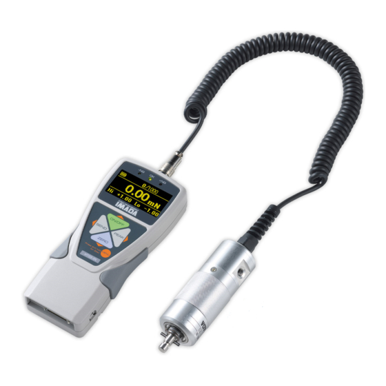
Page 7: Names And Functions
2. Names and Functions An amplifier unit * The design of operation panel is different between HTGS and HTGA. Functions ON/OFF button Turn ON/OFF the power. Select menu. ZERO button Zero values. Select menu. PEAK button Toggle between “Peak mode” and “Track mode”. Select menu. SEND button Save data. - Page 8 2.Names and Functions Display ① ② ③ ① ② ⑥⑦③ Single Display Multi Display ⑧ ⑨ ⑩ ④ ⑥ ⑦ ⑤ ④ ⑤ ① Battery / Battery status ② Displacement value zero / Valid or invalid: Zero displacement value at arbitrary force value. (Refer to page 20, [8.Function Setting, Displacement reset]) (*) ③...
- Page 9 A sensor unit Sensor shaft Sensor grip * Do not loose or tighten this nut. Sensor connector Sensor shaft Installing an attachment to this sensor shaft Sensor grip Hold this part for measurement Sensor connector Connector for connecting with display ●...
-
Page 10: Accessories
3. Accessories The following accessories are included. Make sure to keep them in the carrying case. Carrying case is necessary when transport to protect the torque gauge. ●Instruction manual (This book) ●Inspection certificate ●Warranty ●AC adapter ●Carrying case ●USB cable ●CD-ROM ●Force Recorder Professional Trial Edition CD-ROM (30 days limits) ●Adapter for USB memory (HTGA only) -
Page 11: Preparation
4. Preparation 4.1. Battery and Charge Please charge before your first use of this product. Charging completes in approximately 2 hours when using the included AC adaptor. The battery icon shows the 3 remaining levels. It appears after the power is turned on. Please recharge when it shows It shows an animation of charging while connected with the AC adaptor. -
Page 12: Connection Of Display And Sensor
4. Preparation 4.2. Connection of display and sensor Please connect sensor and display before use. A sensor unit Connector A display unit ●A display unit is calibrated with included sensor. Please do not connect other sensor. ●Do not insert the connector forcibly. -
Page 13: Installation Of An Attachment
4.3. Installation of an attachment Please install suitable attachment to sensor unit. Below image is for installation of HT-DC-6.5. Included set screw After inserting an attachment to sensor shaft, please fix the attachment with included set screw. ●Please pay attention that attachment may fall down if the set screw is not fixed. ●It is not necessary the set screw to tighten too strong... -
Page 14: Basic Operation
5. Basic Operation The display indicates either clockwise or counter-clockwise torque. The measurement is done on Peak mode or Track mode. Functions Operation Description Turn on power. The introduction message shows up first, and measurement can be started after Power on Press the message disappears. -
Page 15: Single Display / Multi Display
6. Single display / Multi display Select either Single display or Multi display. Refer to the page 20 for detail of toggling. 6.1. Single display Display torque value only. *Displacement value can be checked on Multi display (HTGA only). Single display 6.2. - Page 16 6. Single display / Multi display Refer to the page 17 for how to set. Multi Display:Menu on header Contents Description Valid Model Date Date HTGA/HTGS Time Time HTGA/HTGS Number The number of saved force value. HTGA/HTGS of memory The number of force torque exceeding set Number of +NG comparator (High) value.
- Page 17 Multi Display:Menu on footer Contents Description Valid Model Set comparator High / Low values. Enable to set the values with (MENU button) while this Comparator High / HTGA/HTGS content lights on. Change values with Low values (ON/OFF,ZERO button) and enter with (MENU button).
-
Page 18: Initial Setting
7. Initial Setting 1.Turn off power. 2.Hold MENU button)and turn on power with (ON/OFF button). ( 3.Select menu in Main menu with (ON/OFF,ZERO buttons),and go to Sub menu with ( PEAK button).(Some menu doesn’t have Sub menu.) 4.Select menu in Sub menu with ),and go to Setting menu with (ON/OFF,ZERO buttons (PEAK button).Go back to Main menu with... - Page 19 Main menu Sub menu Setting menu Description Valid Initial model setting [N-m] / [N-cm] [Kgf-cm] / HTGA / Force Units [lbf-in] / Change torque units. HTGS [ozf-in] Units (*1) Displacement [°] / [inch] / Change displacement units HTGA ° Units [mm](*1)...
- Page 20 7. Initial Setting Main menu Sub menu Setting menu Description Valid Initial model setting [Display value] Select data sent to external equipment. [+Peak] / [Display value]: Send displayed value. On [-Peak] / multi display the value on the middle display [+/-Peak] / is sent.
- Page 21 Function Setting 1.Hold (MENU button)for more than two seconds while power is on. 2.Select menu in Main menu with ON/OFF,ZERO button),and go to Sub menu with ( (PEAK button).(Some menu doesn’t have Sub menu.) 3.Select menu in Sub menu with ON/OFF,ZERO button),and go to Setting menu with (...
- Page 22 8. Function Setting Function Setting(Program Menu) Main menu Sub menu Setting Description Valid Initial menu model setting Set Hi and Low values. LED and +/- [0000 to High +Capacity 9999] output signal show whether the measurement value is below, within, High / Low Set or above the set values.
- Page 23 Main menu Sub menu Setting menu Description Valid Initial model setting [and] Both clockwise and counter clockwise peak values are displayed in order of clockwise peak, counter clockwise peak, [and] [or] torque value, with (PEAK HTGA / [and] / [or] Peak button).
- Page 24 8. Function Setting Main menu Sub menu Setting menu Description Valid Initial model setting The condition to zero displacement value. [Once] Rest displacement value once when [OFF] / Reset the torque value reaches to the set [Once] / Condition reset value after zero values. Displacement [Each time] [Each time]...
- Page 25 Main menu Sub menu Setting menu Description Valid Initial model setting [Single Display] Display torque value only. [Multi Display] Display HTGA / Multi [Single Display] / Display torque value on the middle Format HTGS Display [Multi Display] display. The contents on the header and footer are selectable.
-
Page 26: Measurement Of Displacement (Htga Only)
9. Measurement of Displacement (HTGA only) HTGA series can detect both force and displacement values. (A displacement meter needed.) Displacement Type is [OFF] at default. Select appropriate Displacement Type depending on displacement meters. 9.1. Connecting to IMADA Test Stand with Liner Scale Instruction manuals of test stands explain types of liner scales. - Page 27 It uses phaseA and phaseB together to know the direction. It reads incremental signals input in the 2 phases. An up/down edge is regarded as 1 count, in other words, please input a quarter of 1 signal period. For example In the case when you combine a HTGA with the displacement scale which uses line driver output with 20μm signal period.
- Page 28 9. Measurement of Displacement (HTGA only) 9.3. Display of displacement The displacement is displayed on the header on Multi display. Please refer to the page 14 for setting. 9.4. Display of displacement at peak torque This function is recommended when graphing is not needed such as peak measurement. When displacement is displayed on the header at Peak mode on Multi display, the displacement at peak torque is displayed.
-
Page 29: Peak Value
10. Peak Value Press (PEAK button) and [P] or [Peak] is displayed at left side of display. [P] and [Peak] mean Peak mode. ●In case of [OR] at Peak mode, higher peak value among clockwise and counter clockwise peak values is displayed. -
Page 30: St / 2Nd Peak Value (Htga Only)
11. 1st / 2nd Peak Value (HTGA only) The peaks of the first and the second curves, instead of the peak of whole measurement, can be detected. The 1st peak as [P1] and the 2nd peak as [P2] are displayed on the footer on Multi display. Torque Time The peak of curve is detected when torque value... -
Page 31: Output
12. Output 12.1. Output to USB memory: HTGA series only HTGA can be connected to USB memory (excluded) using the included adapter. Data of internal memory can be sent to USB memory and measuring data of both real time and a single data can be saved in USB memory. - Page 32 12. Output 12.1.2. Data transport Transport data in the internal memory to USB memory. Program Menu USB Memory Export to USB The following message shows up during transport. (Do not remove the USB memory.) The message disappears when transport ends. * Data in the internal memory is not deleted when transported.
- Page 33 12.1.4. Saving single data A single data is saved to USB memory when ‘Single Data’ is selected in the settings. The data cannot be saved in the internal memory. How to save While (MEM sign) is on, press (SEND button) to save the data of which selected in 【SEND Functions】-【Send Data Select】.
-
Page 34: Usb Output (Output To Pc)
12. Output 12.2. USB output (output to PC) HTGA / HTGS can be connected to PC with included USB cable. The connection with PC using the included data logger CD-ROM is as follows. 12.2.1. Operation environment See the label on the CD-ROM for the details of its operating environment. 12.2.2. -
Page 35: Output On Rs232C/Usb
12.2.4. Installation of data logger software Force Logger After you complete installation of the driver, install Force Logger. You can see how to install it in “The Installation Instruction for Device Driver and Force Logger” in CD-ROM. ●Some PC and environment may not correspond to the CD-ROM. Please get a contact with your local distributor or us in this case. -
Page 36: Analog Output
12. Output 12.4. Analog output 12.4.1. Analog output: D/A (standard spec.) Analog voltage is always output depending on measuring force value. (+/- 2V when max. torque is applied.) Torque value can be recorded at real time by connecting to external equipments with analog cable (excluded). -
Page 37: Wireless Transmission Adapter ( Sold Separately )
12.5. Wireless Transmission Adapter (sold separately) Output This instrument is compatible with a *Wireless Transmission Adapter (*sold separately) for the Wireless Transmission of the measurement values. Settings as follows: [Setup Menu] – [Wireless Setting] – [Wireless Output] – [ON] When the Wireless Output ON, the following operations are restricted: RS-232C communication External SEND input, The combination with the USB memory output function... -
Page 38: Maintenance
13. Maintenance 13.1. Battery Change The display unit has rechargeable battery inside. If the battery is worn out soon after charging or not charged at all, the battery is dying. Please change the batteries. (Battery model: BP-308) The direction is as follows. Turn off the display unit. -
Page 39: Calibration And Repair
13.2. Calibration and Repair We offer calibration service with charge. To maintain the best accuracy and reliable measurement, the periodical calibration is recommended. Please ask your local distributor about fee and lead time. Please note that the function setting (Program Menu) and saved data may be erased when repaired. Please make sure to send the this instrument with the carrying case to protect the gauge. -
Page 40: Specifications
15. Specifications Model HTGA HTGS Advanced model with various functions such Standard model with the same benefit in Feature as data saving in USB memory stick, performance as HTGA series but reduced displacement I/O and more. functions. Accuracy +/-0.5%F.S.+/-1digit Unit of measurement N-m, N-cm,Kgf-cm,lbf-in,ozf-in Display 4-digit with sign... -
Page 41: Optional Items
16. Optional Items Expand the usage with various attachments Pin chuck Socket holder Torque driver M10 adapter Suitable to fix shaft and rod type Suitable to fix torque Suitable to measure tightening Adaptable samples wrench and loosing torque female attachment Large pin chuck Socket holder Torque driver... - Page 42 ○ ○ 5 graphs (max.) can be displayed in a table. - Force-Displacement graphing ○ - - *Angle scale is necessary for force-displacement using professional version. 16. Optional Items Optional cables Model Function Description CB-108 Analog cable Connection with multi meter, oscilloscope and so on. Optional cables CB-118 Analog cable (for option code-AN)
-
Page 43: Dimensions
17. Dimensions ■An display unit... - Page 44 17. Dimensions ■A sensor unit HTGS(HTGA)-2N-m、HTGS(HTGA)-5N-m HTGS(HTGA)-10N-m...
-
Page 45: Output Data
18. Output Data 18.1. Output connector Connector pin arrangement Pin number Signal name Description Model High Low set points of comparator output. Either signal is output depending on comparator HTGA/HTGS judgment. (*1) (*4) Output depending on set high / low output values. (*1) HTGA (*5) Overload output. - Page 46 18. Output Data Pin number Signal name Description Model optional EXSW1:POWER HTGA/HTGS Input signal EXSW2:ZERO HTGA/HTGS The functions differ depending on signal of Shift. EXSW3:SEND HTGA/HTGS Refer to the bottom of the page for detail. EXSW4:PEAK HTGA/HTGS (Detect edge signal when each pin connected to HTGA/HTGS GND pin #30.) (*4) Shift...
-
Page 47: Connection Example Of I/Oterminals
18.2. Connection example of I/O terminals Connection example to output terminal of this instrument 1-7: Output terminal Max.source:less than 30V Inside of the gauge Max.current:less than 10mA Output grand Connection example to input terminal of this instrument 24-29, 31: Current less than 10mA Input terminal Ex.Switch Dry contact input. -
Page 48: File Format Saved In Then Usb Memory (Htga Only)
18. Output Data 18.3. File Format saved in then USB memory (HTGA only) The file format saved in USB memory is as follows. The files are saved in root directory of USB memory. File Format Description File name: The continuous numbers follow after [R]. Each number is followed by comma and File name: R00001.csv saved in CSV style. -
Page 49: Command (Rs232C / Usb)
18.4. Command (RS232C / USB) Setting Contents Format Example Description Category Command Receive Setting Pair of Integer With Comparator XCW[±UUUU] sign (*1) ○ ○ XCW+0100-0100 High / Low [±LLLL] [+/-UUUU]: High [+/-LLLL]: Low Pair of integer with High / Low output XCS[±FFFF] sign (*1) (*2) ○... - Page 50 18. Output Data Setting Contents Format Example Description Category Command Receive Setting Rest peak force value ○ - - and its displacement Reset measuring ○ - - force value Reset measuring Only for HTGA ○ - - displacement value Reset peak, force, ○...
- Page 51 Setting Contents Format Example Description Category Command Receive Setting 1+123.4+ Refer to appended Q±fffff± 123456701L00 chart 1 for format. 1st peak / 2nd peak output ○ - dddddddPLCSX 2+123.4+ (Force and displacement) 123456701L00 Refer to appended Continuous data output Q±fffff± l+123.4+ ○...
- Page 52 18. Output Data Setting Contents Format Example Description Category Command Receive Setting FFFFF:4 digits force Data output value with decimal point (Interchangeable ○ - ±FFFFFUMC +123.4NTO U:Unit number with HTG2/HTG2-P format) M:Current mode C:Comparator judgment ○ Save data - - ○...
- Page 53 Setting Contents Format Example Description Category Command Receive Setting Change to Peak Mode Operation depends [OR]: Display the on the setting of measuring value PEAK button. => either higher value among ○ +/-peak values. - [AND]: Display the measuring value =>...
- Page 54 18. Output Data Appended Chart 1. Format of force response Q±fffff±dddddddPLCSX [Measuring value / Peak value] m±fffff±dddddddPLCSYYMMDDhhmmss [Saved data] Description of respond data format Continuous output Measuring value (Approx. 2000data/sec.) Continuous output Measuring value (Approx. 10data/sec.) a Continuous output +peak value h Continuous output -peak value Status of requested force data r Measuring value...
- Page 55 Appended chart 3. Appended chart 2. Unit list Unit setting numbers and units of displacement *Setting units are different depending on models. * Setting units are different depending on models. No Unit inch(*) ° *Units selection differs between Japan model and on-Japan model.
- Page 56 Yarn Package Durometer and Shore-A Durometer Sample Cutter Balance Moisture Meter Leak Tester Softometer More than 70 years - Worldwide - Hans Schmidt & Co GmbH Phone: e-mail: Mailing address: int. + 49 / (0)8638 / 9410-0 info@hans-schmidt.com P. O. B. 1154...
Need help?
Do you have a question about the HTG Series and is the answer not in the manual?
Questions and answers