Table of Contents
Advertisement
Quick Links
Advertisement
Table of Contents

Subscribe to Our Youtube Channel
Related Manuals for National Instruments PXIe-8238


Summary of Contents for National Instruments PXIe-8238
- Page 1 PXIe-8238 Getting Started 2022-07-06...
-
Page 2: Table Of Contents
PXIe-8238 Front Panel........... 6 Removing the PXIe-8238 from a PXI Express Chassis......8 Cleaning. -
Page 3: Pxie-8238 Getting Started Guide
It also describes the module's front panel connectors. Unpacking The PXIe-8238 ships in an antistatic package to prevent electrostatic discharge from damaging device components. To prevent such damage when handling the device, ground yourself using a grounding strap or by holding a grounded object, such as your computer chassis, and complete the following steps: 1. -
Page 4: Electrical
Hardware Installation The following are general instructions for installing the PXIe-8238. Complete the following steps to install the PXIe-8238 in your PXI Express chassis. 1. Power off your PXI Express chassis, but leave it plugged in while installing the PXIe-8238. The power cord grounds the chassis and protects it from electrical damage while you install the module. - Page 5 5. Identify the slot in which the PXIe-8238 will be installed in the chassis. Refer to the following table to determine which slot types the PXIe-8238 is compatible with.
-
Page 6: Powering On The Pxie-8238
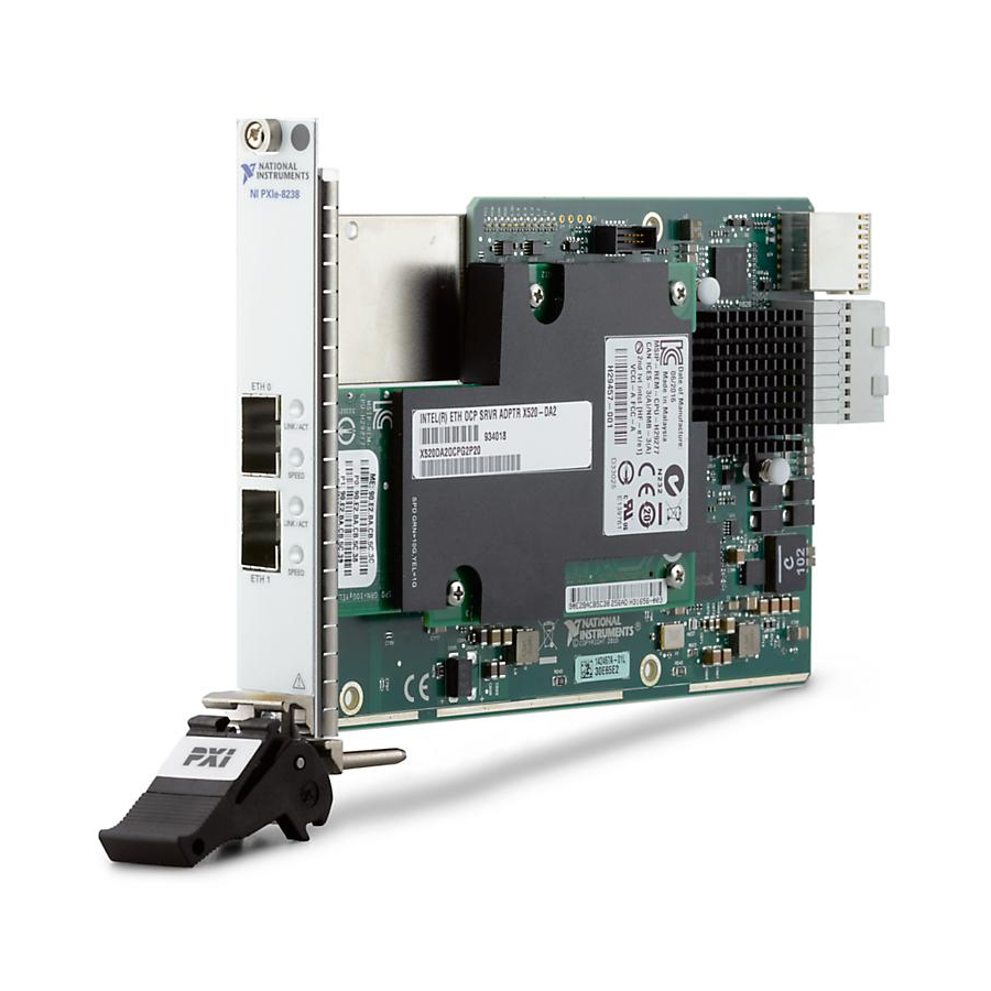
PXIe-8238 Getting Started Powering On the PXIe-8238 The PXIe-8238 powers on automatically when the chassis is powered on. To power on the PXIe-8238, turn on the chassis. Powering Off the PXIe-8238 The PXIe-8238 powers off automatically when the chassis is powered off. You also can power off the PXIe-8238 by shutting down the system controller. - Page 7 ETH 1 1. Ethernet Connector 2. LINK/ACT LED 3. SPEED LED Front Panel Connectors The following table lists various peripherals and their corresponding PXIe-8238 external connectors, bus interfaces, and functions. Peripheral External Connector Description Ethernet Port SFP+ 1 Gb/10 Gb Ethernet based on Intel 82599 10 GbE controller...
-
Page 8: Removing The Pxie-8238 From A Pxi Express Chassis
5. Slide the module out of the chassis. Cleaning Use a dry, low-velocity stream of air to clean the PXIe-8238 module. If needed, use a soft, nonmetallic brush for cleaning around components. Make sure the module is completely dry and free from contaminants before returning it to service. -
Page 9: Ni Services
NI product. Product registration facilitates technical support and ensures that you receive important information updates from NI corporate headquarters is located at 11500 N Mopac Expwy, Austin, TX, 78759-3504, USA. © National Instruments © 2022 National Instruments Corporation.
Need help?
Do you have a question about the PXIe-8238 and is the answer not in the manual?
Questions and answers