
Related Manuals for Gigabyte GS-R22PHE


Summary of Contents for Gigabyte GS-R22PHE
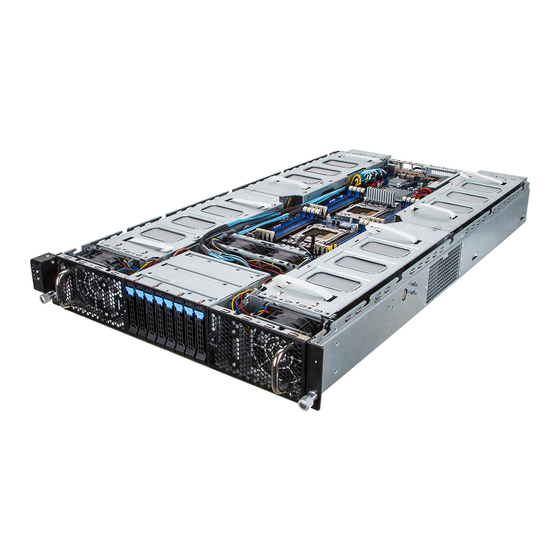
- Page 1 GS-R22PHE Dual LGA2011 socket motherboard for Intel Xeon E5-2600 processors ® ® Service Guide Rev. 1.0...
- Page 2 GIGABYTE's prior written permission. Documentation Classifications In order to assist in the use of this product, GIGABYTE provides the following types of documentations: For detailed product information, carefully read the Serice Guide.
- Page 3 Please note WHEN ORDERING SPARE PARTS, you should check the most up-to-date informationavailable on your regional web or channel. For whatever reason, if a part num- ber change is made,it will not be noted in the printed Service Guide. For GIGABYTE-AU- THORIZED SERVICEPROVIDERS, your GIGABYTE office may have a DIFFERENT part number code to thosegiven in the FRU list of this printed Service Guide.
-
Page 4: Table Of Contents
Table of Contents Box Contents ........................6 Safety, Care and Regulatory Information ................7 Chapter 1 Hardware Installation ...................10 Installation Precautions .................. 10 Product Specifications ..................11 Chapter 2 System Hardware Installation ..............13 Removing Chassis Cover ................14 Removing and Installing the Fan Duct ............15 Installing the CPU .................. - Page 5 Advanced Menu ..................... 49 5-2-1 PCI Configuration ....................50 5-2-1-1 PCI Express Settings ....................52 5-2-2 Runtime Error Logging ...................54 5-2-3 CPU Configuration ....................55 5-2-3-1 CPU Power Management Configuration ..............58 5-2-4 Fan Configuration ....................60 5-2-5 USB Configuration ....................61 5-2-6 SATA Configuration....................62 5-2-7 SAS Configuration ....................64 5-2-8 Info Report Configuration ..................65...
-
Page 6: Box Contents
Box Contents GS-R22PE System Driver CD Heat Sink x 2 Rai Kit • The box contents above are for reference only and the actual items shall depend on the product package you obtain. The box contents are subject to change without notice. •... -
Page 7: Safety, Care And Regulatory Information
Safety, Care and Regulatory Information Important safety information Read and follow all instructions marked on the product and in the documentation before you operateyour sys- tem. Retain all safety and operating instructions for future use. • The product should be operated only from the type of power source indicated on the rating label.* If your computer has a voltage selector switch, make sure that the switch is in the proper position foryour area. - Page 8 Federal Communications Commission (FCC) Statement Warning This is a class A product. In a domestic environment this product may cause radiointerfer- enceIn which case the user may be required to take adequate measures. This equipment has been tested and found to comply with the limits for a Class A digital device,pursuant to Part 15 of the FCC Rules.
- Page 9 WEEE Symbol Statement The symbol shown below is on the product or on its packaging, which indicates that this product must not be disposed of with other waste. Instead, the device should be taken to the waste collection centers for activation of the treatment, collection, recycling and disposal procedure. The separate collection and recycling of your waste equipment at the time of disposal will help to conserve natural resources and ensure that it is recycled in a manner that protects human health and the environment.
-
Page 10: Chapter 1 Hardware Installation
Chapter 1 Hardware Installation Installation Precautions The motherboard/system contain numerous delicate electronic circuits and components which can become damaged as a result of electrostatic discharge (ESD). Prior to installation, carefully read the service guide and follow these procedures: • Prior to installation, do not remove or break motherboard S/N (Serial Number) sticker or warranty sticker provided by your dealer. -
Page 11: Product Specifications
1-2 Product Specifications Support for Intel Xeon E5-2600 series processors in the LGA2011 package ® ® L3 cache varies with CPU Supports QuickPath Interconnect up to 8GT/s Enhanced Intel SpeedStep Technology (EIST) Support Intel Virtualization Technology (VT) Chipset Intel C602 (Patsburg-A) Chipset ®... - Page 12 Patsburg-A; no 4 ports SATA Only SATA RAID 5 upgrade ROM 4 ports SATA/SAS 4 ports SATA/SAS * GIGABYTE reserves the right to make any changes to the product specifications and product-related information without prior notice. Hardware Installation - 12 -...
-
Page 13: Chapter 2 System Hardware Installation
Chapter 2 System Hardware Installation Pre-installation Instructions Perform the steps below before you open the server or before you remove or replaceany component. • Back up all important system and data files before performing any hardwareconfiguration. • Turn off the system and all the peripherals connected to it. • Locate the pin one of the CPU. -
Page 14: Removing Chassis Cover
Removing Chassis Cover Before you remove or install the system cover • Make sure the system is not turned on or connected to AC power. Follow these instructions to remove the system cover: Loosen and remove the screws securing the top cover. Slide the back cover toward the rear of the chassis to disengage it. -
Page 15: Removing And Installing The Fan Duct
Removing and Installing the Fan Duct Follow these instructions to remove/install the fan duct: Lift up to remove the fan duct To install the fan duct, align the fan duct with the guiding groove. Push down the fan duct into chassis until its firmly seats - 15 - Hardware Installation... -
Page 16: Installing The Cpu
Installing the CPU Read the following guidelines before you begin to install the CPU: • Make sure that the motherboard supports the CPU. • Always turn off the computer and unplug the power cord from the power outlet before installing the CPU to prevent hardware damage. -
Page 17: Installing The Heat Sink
Installing the Heat Sink Follow these instructions to install the heat sinks: Apply thermal compound evenly on the top of the CPU. Remove the protective cover from the underside of the heat sink. Place the heat sink(s) on top of the CPU and tighten the four positioning screws. CPU0 CPU1 CPU0 and CPU1 use the different CPU heat sinks. - Page 18 CPU0 CPU1 P/N: 25ST1-463200-T4R P/N: 25ST1-443101-T4R CPU1 CPU0 Hardware Installation - 18 -...
-
Page 19: Installing The Memory
Installing the Memory Read the following guidelines before you begin to install the memory: • Make sure that the motherboard supports the memory. It is recommended that memory of the same capacity, brand, speed, and chips be used. • Always turn off the computer and unplug the power cord from the power outlet before installing the memory to prevent hardware damage. -
Page 20: Installing A Memory
2-5-2 Installing a Memory Before installing a memory module, make sure to turn off the computer and unplug the power cord from the power outlet to prevent damage to the memory module. Be sure to install DDR3 DIMMs on this motherboard. Follow these instructions to install the Memory: Insert the DIMM memory module vertically into the DIMM slot, and push it down. -
Page 21: Installing The Pci Expansion Card
Installing the PCI Expansion Card • Voltages can be present within the server whenever an AC power source is connected. This voltage is present even when the main power switch is in the off position. Ensure that the system is powered-down and all power sources have been disconnected from the server prior to installing a PCI card. - Page 22 PCIE_1 2 x 3 Power cable (Slot 1) 2 x 4 Power cable For Slot 1 PCIE_2 (Slot 2) 2 x 3 Power cable 2 x 4 Power cable For Slot 2 • If the GPGPU card supports 225W, connect 2 x 4 power cable. •...
- Page 23 For GPU2/GPU3/GPU4/GPU5 Follow these instructions to install PCI Expansion card: Loosen and remove the screws securing the PCI cage. Pull the two plastic handles to lift up the PCI cage from the system. Insert the card into the selected slot and secure the expansion card with screw. Make sure that the card is properly seated.
- Page 24 Hardware Installation - 24 -...
- Page 25 PCIE_2 PCIE_1 (Slot 2) (Slot 1) 2 x 3 Power cable 2 x 4 Power cable For Slot 2 2 x 3 Power cable 2 x 4 Power cable For Slot 1 • Please insert the PCI cage into the selected slot with the correct orientation. See illustrated below for instruction.
-
Page 26: Installing Add-On Card (Gc-Mslz1/Pcie_6/Optional)
2-6-1 Installing Add-on Card (GC-MSLZ1/PCIE_6/Optional) • Voltages can be present within the server whenever an AC power source is connected. This voltage is present even when the main power switch is in the off position. Ensure that the system is powered-down and all power sources have been disconnected from the server prior to installing a PCI card. -
Page 27: Installing Add-On Card (Gc-Mslz2/Pcie_5/Optional)
2-6-2 Installing Add-on Card (GC-MSLZ2/PCIE_5/Optional) • Voltages can be present within the server whenever an AC power source is connected. This voltage is present even when the main power switch is in the off position. Ensure that the system is powered-down and all power sources have been disconnected from the server prior to installing a PCI card. -
Page 28: Installing The Hard Disk Drive
Slide the blank into the bay until it locks into place. CAUTION! We strongly recommand using enterprise level hard disk drive in Gigabyte server system. For more information of recommanded HDDs, please visit Gigabyte website: https://www.gigabyte.com and serach for the specific product QVL from Support & Dowloads. -
Page 29: Replacing The Fan Assemblly
Replacing the FAN Assemblly CAUTION! Before you remove or install the system fan cage, take the steps: • Make sure the system is not turned on or connected to the AC power. • Disconnect all necessary cable connections. Failure to observe these warnings could result in personal injury or damage to the equipment. - Page 30 Airflow direction Hardware Installation - 30 -...
- Page 31 For SYS_FAN1/SYS_FAN2 Follow these instructions to replace the fan assembly: Disconnect fan cable. Lift up the fan assembly from the chassis. Attach the four rubbers on the system fan. Reverse the previous step to install the replacement fan assembly. Airflow direction - 31 - Hardware Installation...
- Page 32 For GPU12E_FAN/GPU56E_FAN (Smart Fan) Follow these instructions to replace the fan assembly: Loosen and remove the screws securing the fan cage. Remove the fan cage out of the system. Loosen and remove the screws securing the fan. Reverse the previous step to install the replacement fan assembly. Airflow direction Hardware Installation - 32 -...
- Page 33 CAUTION! • To avoid fan cable damages, please make sure the fan cables are firmly seated in the groove. - 33 - Hardware Installation...
-
Page 34: Replacing The Power Supply
Replacing the Power Supply CAUTION! • In order to reduce the risk of injury from electric shock, disconnect AC power from the power supply before removing it from the system. Follow these instructions to replace the power supply: Disconnect all power cables. Pull up the power supply handle and press the retaining clip on the right side of the power supply along the direction of the arrow. -
Page 35: Chapter 3 System Appearance
Chapter 3 System Appearance Front View Decription Front panel LED and buttons System fan (GPU78_FAN) 2.5-inch hard disk drive #1 2.5-inch hard disk drive #2 2.5-inch hard disk drive #3 2.5-inch hard disk drive #4 2.5-inch hard disk drive #5 2.5-inch hard disk drive #6 2.5-inch hard disk drive #7 2.5-inch hard disk drive #8... -
Page 36: Rear View
Rear View 9 10 Decription System fan (GPU12E_FAN) VGA port Serial port Power swith button ID switch button Reset button (top)/NMI button (buttom) System status LED 1G LAN port 1G LAN port 10/100 Server management LAN port USB 2.0 ports System fan (GPU56E_FAN) Power supply module cord socket Power supply fan... -
Page 37: Front Panel Led And Buttons
Front Panel LED and Buttons No. Name Color Status Description Green Solid On System is powered on. Green Blink System is in ACPI S1 state (sleep mode) Power button • System is not powered on or in ACPI S5 and LED state (power off) •... -
Page 38: Rear System Lan Leds
Rear System LAN LEDs 1 2 3 5 Critical Name Color Status Description Event Green Solid On System is powered on Green Blink System is in ACPI S1 state (sleep mode) Power button • System is not powered on or in ACPI and LED S5 state (power off) •... -
Page 39: Hard Disk Drive Leds
Hard Disk Drive LEDs HDD Present RAID Color Locate Rebuilding HDD Access Fault (No Access) Green On (*1) Blink (*2) Disk LED No RAID (LED on Back Panel) Amber configuration Green On (*1) (via HBA, PCH) Removed HDD Slot (LED on Back Panel) Amber Green Alternately... -
Page 40: Hard Disk Back Plane Board Jumper Setting
Hard Disk Back Plane Board Jumper Setting BPB_CN_2 BPB_CN_2 A_SEL B_SEL SAS_0-3 BPB_PWR SAS_4-7 A_SEL B_SEL 1-2Close SATA_HDD SATA_HDD 2-3 Close SAS_HDD SAS_HDD Hardware Installation - 40 -... -
Page 41: Cable Routing
Cable Routing 10 10 Suggest Cable Suggest Cable System main power cable CPU 0 12V power cable CPU 1 12V power cable Front switch cable/Front LED cable Mini SAS cable #1 Mini SAS cable #2 Front panel board cable HDD back plane board power cable HDD back plane board cable System fan power cable PMbus/PDB cable... -
Page 42: Chapter 4 Motherboard Components
Chapter 4 Motherboard Components GA-7PPSP1 Motherboard Components 55 58 Item Code Description VGA_1 Rear VGA port F_VGA1 Front VGA header COM2 Front serial port header IPMB IPMB connector COM1 Rear serial port SW_PWR Power swith button SW_ID ID switch button PCIE_6 PCI-E slot 6 (x8 slot/Proprietary/Running at x8) SW_RST_NMI... - Page 43 DDR3_P0_B1 Channel 2 slot 1 (for primary CPU) CPU0 Intel LGA2011 socket (Primary CPU) CPU1 Intel LGA2011 socket (Secondary CPU) DDR3_P1_H1 Channel 4 slot 1 (for secondary CPU) DDR3_P1_H0 Channel 4 slot 0 (for secondary CPU) DDR3_P1_G1 Channel 3 slot 1 (for secondary CPU) DDR3_P1_G0 Channel 3 slot 0 (for secondary CPU) PCIE_4...
-
Page 44: Jumper Setting
Jumper Setting 55 58 Jumper Code Jumper Setting 1-2 Close: Normal operation (Default setting) CLR_CMOS (Clearing CMOS Jumper) 2-3 Close: Clear CMOS data 1-2 Close: ME recovery mode. ME_UPDATE (ME recovery Jumper) 2-3 Close: Normal operation. (Default setting) BIOS_WP 1-2 Close: Normal operation. (Default setting) (BIOS Write Protect 2-3 Close: Enable BIOS write protect function. -
Page 45: Chapter 5 Bios Setup
Chapter 5 BIOS Setup BIOS (Basic Input and Output System) records hardware parameters of the system in the EFI on the motherboard. Its major functions include conducting the Power-On Self-Test (POST) during system startup, saving system parameters and loading operating system, etc. BIOS includes a BIOS Setup program that allows the user to modify basic system configuration settings or to activate certain system features. - Page 46 Main This setup page includes all the items in standard compatible BIOS. Advanced This setup page includes all the items of AMI BIOS special enhanced features. (ex: Auto detect fan and temperature status, automatically configure hard disk parameters.) ...
-
Page 47: The Main Menu
The Main Menu Once you enter the BIOS Setup program, the Main Menu (as shown below) appears on the screen. Use arrow keys to move among the items and press <Enter> to accept or enter other sub-menu. Main Menu Help The on-screen description of a highlighted setup option is displayed on the bottom line of the Main Menu. - Page 48 BIOS Information Project Version Display version number of the project. BIOS Build Date and Time Displays the date and time when the BIOS setup utility was created. BMC Information BMC Firmware Version Display version number of the Firmware setup utility. SDR Reversion Display the SDR reversion information.
-
Page 49: Advanced Menu
Advanced Menu The Advanced menu display submenu options for configuring the function of various hardware components. Select a submenu item, then press Enter to access the related submenu screen. - 49 - BIOS Setup... -
Page 50: Pci Configuration
5-2-1 PCI Configuration BIOS Setup - 50 -... - Page 51 PCI Express Slot #1-1/1-2/2-1/2-2/3-1/3-2/4-1/4-2/5/6 I/O ROM When enabled, this setting will initialize the device expansion ROM for the related PCI-E slot. Options available: Enabled/Disabled. Default setting is Enabled. Onboard LAN1/2 Controller Enable/Disable Onboard LAN1/LAN2 controller . Options available: Enabled/Disabled. Default setting is Enabled. LAN1/2 Option ROM Enable/Disable onboard LAN1/LAN2 device and initialize device expansion ROM.
-
Page 52: Pci Express Settings
5-2-1-1 PCI Express Settings PCI Express Device Register Settings Relaxed Ordering Enable/DIsable PCI Express Device Relaxed Ordering feature. Options available: Enabled/Disabled. Default setting is Disabled. Extended Tag Wnen this feature is enabled, the system will allow device to use 8-bit Tag field as a requester. Options available: Enabled/Disabled. - Page 53 Link Training Retry Define the number of Retry Attempts software wil take to retrain the link if previous training attempt was unsuccessful. Press <+> / <-> keys to increase or decrease the desired values. Link Training Timeout (us) Define the number of Microseconds software will wait before polling 'Link Training' bit in Link Status register.
-
Page 54: Runtime Error Logging
5-2-2 Runtime Error Logging Runtime Error Logging Enable/Disable Runtime error logging support. Options available: Enabled/Disabled. Default setting is Disabled. Memory Corr. Error Threshold (Note) Press <+> / <-> keys to increase or decrease the desired values. PCI Error Logging Support (Note) Enable/Disable PCI Error Logging Support. -
Page 55: Cpu Configuration
5-2-3 CPU Configuration - 55 - BIOS Setup... - Page 56 CPU Information Socket 0/1 CPU Information CPU Type/ Signature / Microcode Patch / Max CPU Speed / Min CPU Speed / Processor Cores / Intel HT Technology / Intel VT-x Technology Displays the technical specifications for the installed processor. Intel HT Technology / Intel VT-x Technology Displays the support information for the installed processor.
- Page 57 Execute Disable Bit When enabled, the processor prevents the execution of code in data-only memory pages. This provides some protection against buffer overflow attacks. When disabled, the processor will not restrict code execution in any memory area. This makes the processor more vulnerable to buffer overflow attacks.
-
Page 58: Cpu Power Management Configuration
5-2-3-1 CPU Power Management Configuration CPU Power Management Configuration Power Technology Configure the power management features. Options available: Disable/Energy Efficient/Custom. Default setting is Custom. EIST (Enhanced Intel SpeedStep Technology) Conventional Intel SpeedStep Technology switches both voltage and frequency in tandem between high and low levels in response to processor load. Options available: Enabled/Disabled. - Page 59 CPU C3/C6 Report (Note) Allows you to determine whether to let the CPU enter C3/C6 mode in system halt state. When enabled, the CPU core frequency and voltage will be reduced during system halt state to decrease power consumption. The C3/C6 state is a more enhanced power-saving state than C1. Options available: Enabled/Disabled.
-
Page 60: Fan Configuration
5-2-4 Fan Configuration Fan Contol Policy Define the fan policies. Options available: Full Speed/Performance/Balanced/Quiet. Default setting is Balanced. Fan Rise Curve Press <+> / <-> keys to increase or decrease the desired values. BIOS Setup - 60 -... -
Page 61: Usb Configuration
5-2-5 USB Configuration USB Configuration USB Module Version Display the USB module verison information. Legacy USB Support Enables or disables support for legacy USB devices. Options available: Auto/Enabled/Disabled. Default setting is Enabled. EHCI Hand-off Enable/Disable EHCI (USB 2.0) Hand-off function. Options available: Enabled/Disabled. Default setting is Disabled. - 61 - BIOS Setup... - Page 62 5-2-6 SATA Configuration BIOS Setup - 62 -...
-
Page 63: Sata Configuration
SATA Configuration SATA Port 0/1/2/3/4/5 (Note) Displays the installed HDD devices information. System will automatically detect HDD type. SATA Mode Select the on chip SATA mode. IDE Mode: When set to IDE, the SATA controller disables its RAID and AHCI functions and runs in the IDE emulation mode. -
Page 64: Sas Configuration
5-2-7 SAS Configuration SAS Configuration SAS Port 0/1/2/3 (Note) Press [Enter] to view the installed HDD devices. (Note) The number of SATA and SAS devices depends of the PCH SKU. BIOS Setup - 64 -... -
Page 65: Info Report Configuration
5-2-8 Info Report Configuration Info Report Configuration Post Report Post Report Enable/Disable Post Report support. Options available: Enabled/Disabled. Default setting is Enabled. Error Message Report Info Error Message Enable/Disable Info Error Message support. Options available: Enabled/Disabled. Default setting is Enabled. - 65 - BIOS Setup... - Page 66 5-2-9 Super IO Configuration BIOS Setup - 66 -...
-
Page 67: Super Io Configuration
Super IO Configuration Super IO Chip Display the model name of Super IO chipset. Serial Port 0/1 Configuration Serial Port When enabled allows you to configure the serial port settings. When set to Disabled, displays no configuration for the serial port. Options available: Enabled/Disabled. Default setting is Enabled. Device Settings Displays the Serial Port base I/O address and IRQ. -
Page 68: Serial Port Console Redirection
5-2-10 Serial Port Console Redirection BIOS Setup - 68 -... - Page 69 COM1/COM2/Serial Port for Out-of Band Management / Windows Emergency Management Service (EMS) Console Redirection (Note) Select whether to enable console redirection for specified device. Console redirection enables users to manage the system from a remote location. Options available: Enabled/Disabled. Default setting is Disabled. Console Redirection Settings Terminal Type Select a terminal type to be used for console redirection.
- Page 70 Stop Bits Stop bits indicate the end of a serial data packet. (A start bit indicates the beginning). The standard setting is 1 stop bit. Communication with slow devices may require more than 1 stop bit. Options available: 1/2. Flow Control Flow control can prevent data loss from buffer overflow.
-
Page 71: Network Stack
5-2-11 Network Stack Network stack Enable/Disable UEFI network stack. Options available: Enabled/DIsabled. Default setting is Disabled. Ipv4 PXE Support (Note) Enable/Disable Ipv4 PXE feature. Options available: Enabled/DIsabled. Default setting is Enabled. Ipv6 PXE Support (Note) Enable/Disable Ipv6 PXE feature. Options available: Enabled/DIsabled. Default setting is Enabled. This item appears when Network Stack is set to Enabled. -
Page 72: Intel (R) I350 Gigabit Network Connection
5-2-12 Intel (R) I350 Gigabit Network Connection BIOS Setup - 72 -... - Page 73 PORT CONFIGURATION MENU NIC Configuration Press [Enter] for configuration of advanced items. Blink LEDs (range 0-15 seconds) Blink LEDs for the specified duration (up to 15 seconds). Press the numberic keys to input the desired value. PORT CONFIGURATION INFORMATION UEFI Driver Display the UEFI driver information.
-
Page 74: Chipset Menu
Chipset Menu The Chipset menu display submenu options for configuring the function of North Bridge and South Bridge. Select a submenu item, then press Enter to access the related submenu screen. BIOS Setup - 74 -... -
Page 75: North Bridge
5-3-1 North Bridge - 75 - BIOS Setup... -
Page 76: Ioh Configuration
IOH Configuration Press [Enter] for configuration of advanced items. QPI Configuration Press [Enter] for configuration of advanced items. Compatibility RID Enable/Disable Compatibility RID function. Options available: Enabled/Disabled. Default setting is Enabled. Memory Configuration Total Memory Displays the total capacity of the installed memory. Current Memory Mode Displays the current memory mode. - Page 77 Data Scrambling Enable/Disable Data Scrambling function. Options available: Enabled/Disabled. Default setting is Enabled. Device Tagging Enable/Disable Device Tagging function. Options available: Enabled/Disabled. Default setting is Disabled. Rank Margin Enable/Disable Rank Margin function. Options available: Enabled/Disabled. Default setting is Disabled. Thermal Thortting Configure theThermal Thortting.
- Page 78 5-3-1-1 IOH Configuration BIOS Setup - 78 -...
- Page 79 IOH Configuration Intel(R) VT for Directed I/O Configuration Press [Enter] for configuration of advanced items. Intel(R) I/OAT (Intel I/O Acceleration Technology) Enable/Disable Intel I/OAT function. Options available: Enabled/Disabled. Default setting is Disabled. DCA Support (Direct Cache Access) Enable/Disable Intel DCA Support function. Options available: Enabled/Disabled. Default setting is Disabled. VGA Priority Define the display device priority.
-
Page 80: Qpi Configuration
5-3-1-2 QPI Configuration Current QPI Link Speed/ Current QPI Link Freq Displays the current QPI Link Speed and Frequency information. Isoc Enable/Disable Isoc. Options available: Enabled/Disabled. Default setting is Disabled. MesegEN Options available: Enabled/Disabled. Default setting is Disabled. QPI Link Speed Mode Configure QPI Link Speed mode. -
Page 81: Dimm Information
5-3-1-3 DIMM Information DIMM Information: DIMM Group: CPU Socket 0/1 DIMM Information CPU Socket 0: DDR3_P0_A0/DDR3_P0_A1/DDR3_P0_B0/DDR3_P0_B1/ DDR3_P0_C0/DDR3_P0_C1/DDR3_P0_D0/DDR3_P0_D1 Status The size of memory installed on each of the DDR3 slots. CPU Socket 1: DDR3_P1_E0/DDR3_P1_E1/DDR3_P1_F0/DDR3_P1_F1/ DDR3_P1_G0/DDR3_P1_G1/DDR3_P1_H0/DDR3_P1_H1 Status The size of memory installed on each of the DDR3 slots. - 81 - BIOS Setup... -
Page 82: South Bridge
5-3-2 South Bridge PCH Information Name/Stepping Information Displays the name and stepping information of the south bridge. SB Chipset Configuration PCH Compatibility RID Enable/Disable PCH Compatibility RID support. Options available: Enabled/Disabled. Default setting is Disabled. Restore on AC Power Loss (Note) Defines the power state to resume to after a system shutdown that is due to an interruption in AC power. When set to Last State, the system will return to the active power state prior to shutdown. - Page 83 High Precision Event Timer Configuration High Precision Event Timer Enable/Disable High Precision Event Timer. Options available: Enabled/Disabled. Default setting is Enabled. - 83 - BIOS Setup...
-
Page 84: Me Subsystem
5-3-3 ME Subsystem Intel ME Subsystem Configuration ME Subsystem Configuration Enable/Disable ME subsystem configuration. Options available: Enabled/Disabled. Default setting is Enabled. BIOS Setup - 84 -... -
Page 85: Security Menu
Security Menu The Security menu allows you to safeguard and protect the system from unauthorized use by setting up access passwords. There are two types of passwords that you can set: • Administrator Password Entering this password will allow the user to access and change all settings in the Setup Utility. •... -
Page 86: Server Management Menu
Server Management Menu OS Watchdog Timer Enable/Disable OS Watchdog Timer function. Options available: Enabled/Disabled. Default setting is Disabled. OS Wtd Timer Timeout Configure OS Watchdog Timer. Options available: 5 minutes/10 minutes/15 minutes/20 minutes. Default setting is 10 minutes. OS Wtd Timer Policy Configure OS Watchdog Timer Policy. -
Page 87: Bmc Lan Configuration
5-5-1 BMC LAN Configuration Lan Channel 1 Configuration Source Select to configure LAN channel parameters statically or dynamically (DHCP). Do nothing option willnot modify any BMC network parameters during BIOS phase. Options available: Static/Dynamic/Do Nothing. IP Address Display IP Address information. Subnet Mask Display Subnet Mask information. -
Page 88: Bmc Function
5-5-2 BMC Function Select NCSI and Dedicated LAN Switch NCSI and dedicated LAN and send KCS command. Options available: Mode2(NSCI)/ Mode1 (Dedicated). Default setting is Mode1 (Dedicated). BIOS Setup - 88 -... -
Page 89: View Fru Information
5-5-3 View FRU Information The System Management submenu is a simple display page for basic system ID information, as well as System product information. Items on this window are non-configurable. - 89 - BIOS Setup... -
Page 90: System Event Log
5-5-4 System Event Log Enabling/Disabling Options SEL Components Change this to enable or disable all features of System Event Logging during boot. Options available: Enabled/Disabled. Default setting is Enabled. Erasing Settings Erasing SEL Choose options for erasing SEL. Options available: No/Yes, On next reset/Yes, On every reset. Default setting is No. When SEL is Full Choose options for reactions to a full SEL. -
Page 91: Boot Menu
Boot Menu The Boot menu allows you to set the drive priority during system boot-up. BIOS setup will display an error message if the legacy drive(s) specified is not bootable. Boot Configuration Setup Prompt Timeout Number of seconds to wait for setup activation key. 65535(0xFFFF) means indefinite waiting." Press the numberic keys to input the desired value. - Page 92 Boot Priority Order Boot Option #1/#2/#3/#4 Press Enter to configure the boot priority. By default, the server searches for boot devices in the following secquence: UEFI device. Hard drive. Network device. Removable device Network Device BBS Priorities Press Enter to configure the boot priority. Hard Drive BBS Priorities Press Enter to configure the boot priority.
-
Page 93: Csm16 Parameters
5-6-1 CSM16 Parameters CSM16 Parameters CSM16 Module Version Display CSM Module version information. Gate20 Active Upon Request: GA20 can be disabled using BIOS services. Always: Do not allow disabling GA20; this option is useful when any RT code is executed above 1MB. Options available: Upon Request/Always. -
Page 94: Csm Parameters
5-6-2 CSM Parameters CSM (Compatibility Support Module) Launch Enable/Disable Compatibility Support Module (CSM) launch. Options available: Enabled/Disabled. Default setting is Enabled. • The following five items appears and configurable when the Launch CSM is set to Enabled. • If the Launch CSM is set to Disabled, the following five items will not be able to support Legacy mode. -
Page 95: Exit Menu
Exit Menu The Exit menu displays the various options to quit from the BIOS setup. Highlight any of the exit options then press Enter. Save Changes and Exit Saves changes made and close the BIOS setup. Options available: Yes/No. Discard Changes and Exit Discards changes made and close the BIOS setup. -
Page 96: Bios Beep Codes
BIOS Beep Codes # of Beeps Description Invalid password Recovery started S3 Resume failed DXEIPL was not found No Console Input/Output Devices are found Flash update is failed - 96 - BIOS Setup... -
Page 97: Bios Recovery Instruction
BIOS Recovery Instruction The system has an embedded recovery technique. In the event that the BIOS becomes corrupt the boot block can be used to restore the BIOS to a working state. To restore your BIOS, please follow the instructions listed below: Recovery Instruction: Change xxx.ROM to amiboot.rom.
Need help?
Do you have a question about the GS-R22PHE and is the answer not in the manual?
Questions and answers