Table of Contents
Advertisement
Quick Links
This user's guide describes the characteristics, operation, and use of the TLV320AIC3109EVM, both by
itself and as part of the TLV320AIC3109EVM-K. This evaluation module (EVM) is a complete mono audio
codec with several inputs and outputs, extensive audio routing, mixing, and effects capabilities. A
complete circuit description, schematic diagram, and bill of materials (BOM) are also included.
The following related documents are available through the Texas Instruments Web site at www.ti.com.
1
2
3
TLV320AIC3109EVM-K Setup and Installation
4
TLV320AIC3109EVM Software
Appendix A
EVM Connector Descriptions
Appendix B
TLV320AIC3109EVM Schematic
Appendix C
TLV320AIC3109EVM Layout Views
Appendix D
Appendix E
USB-MODEVM Schematic
Appendix F
USB-MODEVM Layout Views
Appendix G
Appendix H
TLV320AIC3109-Q1 Configuration Scripts
Appendix I
USB-MODEVM Protocol
1
TLV320AIC3109EVM Block Diagram
2
TLV320AIC3109EVM Board
3
USB-MODEVM Board
4
5
6
7
8
9
10
11
.................................................................................................................
12
Microsoft, Windows are registered trademarks of Microsoft Corporation.
SPI is a trademark of Motorola, Inc.
VISA, LabVIEW are trademarks of National Instruments Corporation.
All other trademarks are the property of their respective owners.
SLAU738 - September 2017
Submit Documentation Feedback
Table 1. EVM-Compatible Device Data Sheets
Device
TLV320AIC3109-Q1
TPS73533-Q1
TAS1020B
...............................................................................................................
...............................................................................................
...........................................................................................
....................................................................................
................................................................................
.......................................................................................
...................................................................................
.................................................................................
.........................................................................................
....................................................................................
...............................................................................................
.......................................................................................................
.................................................................................................
..................................................................................................
................................................................................................
...............................................................................................................
.......................................................................................................
Copyright © 2017, Texas Instruments Incorporated
TLV320AIC3109EVM-K
Literature Number
SLASE93
SBVS252
SLES025
Contents
........................................................................
............................................................................
..........................................................................
....................................................................
List of Figures
.............................................................................
............................................................................
.............................................................................
User's Guide
SLAU738 - September 2017
3
6
12
13
33
37
40
43
45
47
49
51
56
3
4
5
9
10
11
14
14
16
17
18
19
1
TLV320AIC3109EVM-K
Advertisement
Table of Contents

Subscribe to Our Youtube Channel
Related Manuals for Texas Instruments TLV320AIC3109EVM-K


Summary of Contents for Texas Instruments TLV320AIC3109EVM-K
-
Page 1: Table Of Contents
This user's guide describes the characteristics, operation, and use of the TLV320AIC3109EVM, both by itself and as part of the TLV320AIC3109EVM-K. This evaluation module (EVM) is a complete mono audio codec with several inputs and outputs, extensive audio routing, mixing, and effects capabilities. A complete circuit description, schematic diagram, and bill of materials (BOM) are also included. - Page 2 Power Supply Pinout ................... TLV320AIC3109EVM Bill of Materials ..................USB-MODEVM Bill of Materials ..............USB Control Endpoint HIDSETREPORT Request ....................Data Packet Configuration ....................GPIO Pin Assignments TLV320AIC3109EVM-K SLAU738 – September 2017 Submit Documentation Feedback Copyright © 2017, Texas Instruments Incorporated...
-
Page 3: Evm Overview
TLV320AIC3109EVM and a USB-based motherboard called the USB-MODEVM Interface board. The TLV320AIC3109EVM-K is operational with one USB cable connection to a personal computer. The USB connection provides power, control, and streaming audio data to the EVM kit for reduced setup and configuration. - Page 4 1.2.1.1 TLV320AIC3109EVM The TLV320AIC3109EVM showcases the latest Texas Instruments (TI) mono audio codec, the TLV320AIC3109-Q1 (U3). The TLV320AIC3109-Q1 device is a low-power mono audio codec with a mono headphone amplifier and multiple input and output channels that are programmable in single-ended or fully differential configurations.
- Page 5 In the factory configuration, the board is ready to use with the TLV320AIC3109EVM. To view all the functions and configuration options available on the USB-MODEVM board, see the USB-MODEVM Interface Board schematic in Appendix Figure 3. USB-MODEVM Board SLAU738 – September 2017 TLV320AIC3109EVM-K Submit Documentation Feedback Copyright © 2017, Texas Instruments Incorporated...
-
Page 6: Evm Description And Basics
Connects analog and digital grounds on the lower part the board Installed Connects analog and digital grounds on the upper part the board Open Selects onboard EEPROM as firmware source TLV320AIC3109EVM-K SLAU738 – September 2017 Submit Documentation Feedback Copyright © 2017, Texas Instruments Incorporated... - Page 7 VD comes from U2 JMP7 When connecting 1-2, MCLKI comes from USB; when connecting 2-3, MCLKI comes from AVSS and DVSS JMP8 Open Connects resistor across EXT MCLK SLAU738 – September 2017 TLV320AIC3109EVM-K Submit Documentation Feedback Copyright © 2017, Texas Instruments Incorporated...
- Page 8 Refer to section Section 4.9 for more details on the headphone output mode configuration. The analog output section of the EVM is shown in Figure TLV320AIC3109EVM-K SLAU738 – September 2017 Submit Documentation Feedback Copyright © 2017, Texas Instruments Incorporated...
-
Page 9: Analog Section Of The Tlv320Aic3109Evm
Headers to set CAPLESS or AC-Coupled HP Output Terminal Out-of-Band Noise Low Pass Filter Left and Right Line Output Terminals Figure 4. Analog Section of the TLV320AIC3109EVM SLAU738 – September 2017 TLV320AIC3109EVM-K Submit Documentation Feedback Copyright © 2017, Texas Instruments Incorporated... -
Page 10: Digital Section Of The Tlv320Aic3109Evm
The EVM can be powered by external power supplies when being used in stand-alone operation or by the USB-MODEVM when it is plugged onto the motherboard. The following sections discuss each operation mode. TLV320AIC3109EVM-K SLAU738 – September 2017 Submit Documentation Feedback Copyright © 2017, Texas Instruments Incorporated... -
Page 11: Power Supplies For Stand-Alone Operation
If +1.8 VD and +3.3 VD are supplied externally, disable the onboard regulators by placing SW1 switches in the OFF position. Each power supply voltage has an LED (D1–D7) that lights when the power supplies are active. SLAU738 – September 2017 TLV320AIC3109EVM-K Submit Documentation Feedback Copyright © 2017, Texas Instruments Incorporated... - Page 12 TLV320AIC3109EVM-K Setup and Installation www.ti.com TLV320AIC3109EVM-K Setup and Installation The following section provides information on using the TLV320AIC3109EVM-K, including set up, program installation, and program usage. NOTE: If using the EVM in stand-alone mode, the software should be installed per Section 3.1, but...
- Page 13 A progress bar should appear and show the status of the configuration. SLAU738 – September 2017 TLV320AIC3109EVM-K Submit Documentation Feedback Copyright © 2017, Texas Instruments Incorporated...
-
Page 14: Device Selection Window
TLV320AIC3104 GUI are not available for the TLV320AIC3109-Q1 evaluation. TI recommends not changing any of the parameters in these sections, otherwise, the performance and behavior of the device cannot be assured. Figure 8. Default Software Screen TLV320AIC3109EVM-K SLAU738 – September 2017 Submit Documentation Feedback Copyright © 2017, Texas Instruments Incorporated... - Page 15 AGC Gain Applied indicators use a bar graph to show the amount of gain which has been applied by the AGC, and indicators that light when the AGC is saturated. SLAU738 – September 2017 TLV320AIC3109EVM-K Submit Documentation Feedback Copyright © 2017, Texas Instruments Incorporated...
-
Page 16: Audio Input And Adc Tab
(excluding Mute). At the extreme counterclockwise rotation, the channel is muted. Rotating the knob clockwise increases the PGA gain, which is displayed in the box directly above the volume control. TLV320AIC3109EVM-K SLAU738 – September 2017 Submit Documentation Feedback Copyright © 2017, Texas Instruments Incorporated... -
Page 17: Bypass Paths
The active bypass paths allow the inputs to bypass the ADC and DAC functional blocks and be routed to the analog output mixers to be summed into the output amplifiers. The Bypass Paths tab is shown in Figure Figure 10. Bypass Paths SLAU738 – September 2017 TLV320AIC3109EVM-K Submit Documentation Feedback Copyright © 2017, Texas Instruments Incorporated... -
Page 18: Audio Interface Tab
(BCLK and WCLK are supplied to the codec externally). For use with the PC software and the USB- MODEVM, the default settings should be used; no change to the software is required. TLV320AIC3109EVM-K SLAU738 – September 2017 Submit Documentation Feedback Copyright © 2017, Texas Instruments Incorporated... -
Page 19: Clocks Tab
TLV320AIC3109-Q1 Automotive, Low-Power, 96-kHz, Mono Audio Codec, the codec should be configured to allow the value of Fsref to fall between the values of 39 kHz to 53 kHz. SLAU738 – September 2017 TLV320AIC3109EVM-K Submit Documentation Feedback Copyright © 2017, Texas Instruments Incorporated... - Page 20 ADC or DAC by pressing the corresponding Dual Rate Mode button. The ADC and DAC sampling rates are shown in the box to the right of each control. TLV320AIC3109EVM-K SLAU738 – September 2017 Submit Documentation Feedback Copyright © 2017, Texas Instruments Incorporated...
-
Page 21: Agc Tab
Figure 14. Advanced AGC settings SLAU738 – September 2017 TLV320AIC3109EVM-K Submit Documentation Feedback Copyright © 2017, Texas Instruments Incorporated... -
Page 22: Filters Tab
Note that the plot shows only the responses of the effect filters, not the combined response of those filter along with the de-emphasis and ADC high-pass filters. TLV320AIC3109EVM-K SLAU738 – September 2017 Submit Documentation Feedback Copyright © 2017, Texas Instruments Incorporated... -
Page 23: Adc High Pass Filters
The DAC Filters tab is shown in Figure 17. Detailed information about the different configuration options for the DAC filters is discussed in the following sections. Figure 17. DAC Filters SLAU738 – September 2017 TLV320AIC3109EVM-K Submit Documentation Feedback Copyright © 2017, Texas Instruments Incorporated... -
Page 24: De-Emphasis Filters
19, in Bass mode a shelf filter applies a gain to frequencies below the corner frequency; in Treble mode the gain is applied to frequencies above the corner frequency. TLV320AIC3109EVM-K SLAU738 – September 2017 Submit Documentation Feedback Copyright © 2017, Texas Instruments Incorporated... -
Page 25: Eq Filters
Parameter entry boxes appropriate to the filter type are shown (ripple, for example, with Chebyshev filters, and so forth). Enter the desired design parameters and the response is shown. The Analog Simulation Filters tab is shown in Figure SLAU738 – September 2017 TLV320AIC3109EVM-K Submit Documentation Feedback Copyright © 2017, Texas Instruments Incorporated... -
Page 26: Preset Filters
If filter coefficients are known, they can be entered directly on this tab for both biquads. The filter response will not be shown on the Effect Filter Response graph for user filters. The User Filters tab is depicted in Figure Figure 23. User Filters TLV320AIC3109EVM-K SLAU738 – September 2017 Submit Documentation Feedback Copyright © 2017, Texas Instruments Incorporated... -
Page 27: Output Stage Configuration Tab
Output Stage Configuration Tab The Output Stage Configuration tab (shown in Figure 25) allows the setting of different features of the output drivers. Figure 25. Output Stage Configuration Tab SLAU738 – September 2017 TLV320AIC3109EVM-K Submit Documentation Feedback Copyright © 2017, Texas Instruments Incorporated... -
Page 28: 4.10 Dac/Line Outputs Tab
The DAC/Line Outputs tab controls the DAC power and volume, as well as routing of digital data to the DAC and the analog line output from the DAC. The default configuration of the DAC/Line Outputs tab is shown in Figure TLV320AIC3109EVM-K SLAU738 – September 2017 Submit Documentation Feedback Copyright © 2017, Texas Instruments Incorporated... - Page 29 NOTE: If the DAC Output Path control is set to anything other than Mix with Analog Inputs, these controls have no effect. SLAU738 – September 2017 TLV320AIC3109EVM-K Submit Documentation Feedback Copyright © 2017, Texas Instruments Incorporated...
-
Page 30: 4.11 High-Power Outputs Tab
TLV320AIC3109EVM are included in Appendix H. These scripts can be loaded into the EVM by using the Command Line Interface tab, shown in Figure TLV320AIC3109EVM-K SLAU738 – September 2017 Submit Documentation Feedback Copyright © 2017, Texas Instruments Incorporated... -
Page 31: 4.13 Command Line Interface Tab
The log file is a standard text file that can be opened with any text editor, and looks much like the source script file, but with the additional information of the result of each script command executed. SLAU738 – September 2017 TLV320AIC3109EVM-K Submit Documentation Feedback Copyright © 2017, Texas Instruments Incorporated... -
Page 32: File Menu
The actual USB protocol used as well as instructions on writing scripts are detailed in the following subsections. While it is not necessary to understand or use either the protocol or the scripts directly, understanding them may be helpful to some users. TLV320AIC3109EVM-K SLAU738 – September 2017 Submit Documentation Feedback Copyright © 2017, Texas Instruments Incorporated... - Page 33 AGND Analog ground J2.10 RIGHT_LOP Right-line output (plus) J2.11 AGND Analog ground J2.12 RIGHT_LOM Right-line output (minus) J2.13 AGND Analog ground J2.14 Not connected SLAU738 – September 2017 EVM Connector Descriptions Submit Documentation Feedback Copyright © 2017, Texas Instruments Incorporated...
- Page 34 LINE2 (–) AGND LINE1 (+) LINE1 (–) AGND AGND HPCOM (–) HPOUT (+) LEFT OUT (+) LEFT OUT (–) RIGHT OUT (+) RIGHT OUT (–) EVM Connector Descriptions SLAU738 – September 2017 Submit Documentation Feedback Copyright © 2017, Texas Instruments Incorporated...
- Page 35 J5.15 Not connected J5.16 C serial clock J5.17 MCLK Master clock input J5.18 DGND Digital ground J5.19 Not connected J5.20 C Serial Data I/O SLAU738 – September 2017 EVM Connector Descriptions Submit Documentation Feedback Copyright © 2017, Texas Instruments Incorporated...
- Page 36 The TLV320AIC3109EVM motherboard (the USB-MODEVM Interface board) supplies power to J3 of the TLV320AIC3109EVM. Power for the motherboard is supplied either through its USB connection or via terminal blocks on that board. EVM Connector Descriptions SLAU738 – September 2017 Submit Documentation Feedback Copyright © 2017, Texas Instruments Incorporated...
-
Page 37: Tlv320Aic3109-Q1 Main Schematics
RIGHT- JACK TP34 TP35 AGND RIGHT_LOM RIGHT- 0.047µF AGND ON-BOARD MIC ENABLE AGND Copyright © 2017, Texas Instruments Incorporated AGND Figure 30. TLV320AIC3109-Q1 Main Schematics SLAU738 – September 2017 TLV320AIC3109EVM Schematic Submit Documentation Feedback Copyright © 2017, Texas Instruments Incorporated... -
Page 38: Connector, Test Points, And Power Distribution Schematics
J2-20 J5-19 AGND DGND DOUT DOUT AGND DGND TEST POINTS Copyright © 2017, Texas Instruments Incorporated Figure 31. Connector, Test Points, and Power Distribution Schematics TLV320AIC3109EVM Schematic SLAU738 – September 2017 Submit Documentation Feedback Copyright © 2017, Texas Instruments Incorporated... -
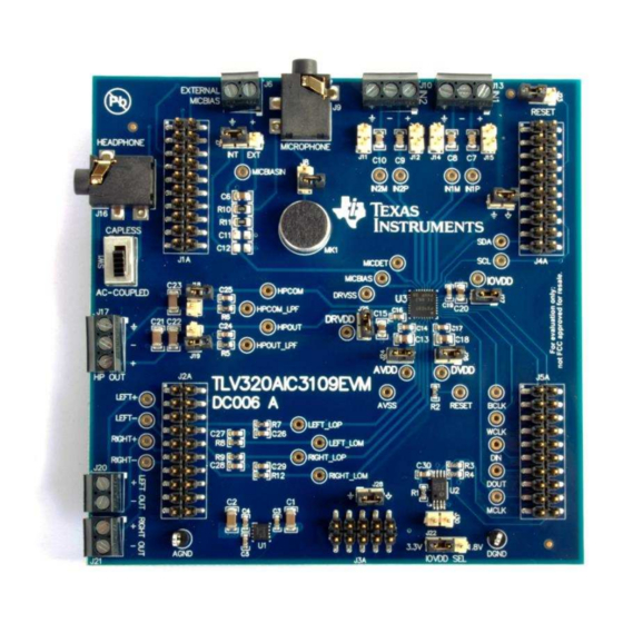
Page 39: Tlv320Aic3109Evm Hardware
These assemblies are ESD sensitive, ESD precautions shall be observed Assembly Note These assemblies must be clean and free from flux and all contaminants. use of no clean flux is not acceptable. Copyright © 2017, Texas Instruments Incorporated Figure 32. TLV320AIC3109EVM Hardware SLAU738 – September 2017... -
Page 40: Tlv320Aic3109Evm Assembly Layer
The board layouts for the modular TLV320AIC3109EVM are illustrated in Figure 33 through Figure Figure 33. TLV320AIC3109EVM Assembly Layer Figure 34. TLV320AIC3109EVM Top Layer TLV320AIC3109EVM Layout Views SLAU738 – September 2017 Submit Documentation Feedback Copyright © 2017, Texas Instruments Incorporated... -
Page 41: Tlv320Aic3109Evm Ground Layer
Appendix C www.ti.com Figure 35. TLV320AIC3109EVM Ground Layer Figure 36. TLV320AIC3109EVM Power Layer SLAU738 – September 2017 TLV320AIC3109EVM Layout Views Submit Documentation Feedback Copyright © 2017, Texas Instruments Incorporated... -
Page 42: Tlv320Aic3109Evm Bottom Layer
Appendix C www.ti.com Figure 37. TLV320AIC3109EVM Bottom Layer Figure 38. TLV320AIC3109EVM Bottom Assembly Layer TLV320AIC3109EVM Layout Views SLAU738 – September 2017 Submit Documentation Feedback Copyright © 2017, Texas Instruments Incorporated... -
Page 43: Tlv320Aic3109Evm Bill Of Materials
Texas Instruments 500-mA, Low Quiescent Current, Low-Noise, High DRB0008B PSRR, Low-Dropout Linear Regulator for Automotive, DRB0008B (VSON-8) 24LC512-I/ST Microchip EEPROM, 512KBIT, 400KHZ, 8TSSOP TSSOP-8 SLAU738 – September 2017 TLV320AIC3109EVM Bill of Materials Submit Documentation Feedback Copyright © 2017, Texas Instruments Incorporated... - Page 44 TP13, TP14, TP15, TP16, TP17, TP18, TP19, TP20, TP21, TP22, TP23, TP24, TP25, TP26, TP27, TP28, TP29, TP30, TP31, TP32, TP33, TP34, TP35 TLV320AIC3109EVM Bill of Materials SLAU738 – September 2017 Submit Documentation Feedback Copyright © 2017, Texas Instruments Incorporated...
-
Page 45: Usb-Modevm Interface Board Schematic (1 Of 2)
DOCUMENT CONTROL NO. 6463996 SIZE DATE 3-Apr-2007 SHEET FILE C:\Work\USB-MODEVM\USB Motherboard - ModEvm.ddb - Documents\SCH\USB Interface Figure 39. USB-MODEVM Interface Board Schematic (1 of 2) SLAU738 – September 2017 USB-MODEVM Schematic Submit Documentation Feedback Copyright © 2017, Texas Instruments Incorporated... -
Page 46: Usb-Modevm Interface Board Schematic (2 Of 2)
DOCUMENT CONTROL NO. 6463996 SIZE DATE 3-Apr-2007 SHEET FILE C:\Work\USB-MODEVM\USB Motherboard - ModEvm.ddb - Documents\SCH\Daughtercard Interface Figure 40. USB-MODEVM Interface Board Schematic (2 of 2) USB-MODEVM Schematic SLAU738 – September 2017 Submit Documentation Feedback Copyright © 2017, Texas Instruments Incorporated... -
Page 47: Usb-Modevm Assembly Layer
Appendix F SLAU738 – September 2017 USB-MODEVM Layout Views The USB-MODEVM interface board layouts (included only in the TLV320AIC3109EVM-K) are illustrated in Figure 41 through Figure Figure 41. USB-MODEVM Assembly Layer SLAU738 – September 2017 USB-MODEVM Layout Views Submit Documentation Feedback... -
Page 48: Usb-Modevm Top Layer
Appendix F www.ti.com Figure 42. USB-MODEVM Top Layer Figure 43. USB-MODEVM Bottom Layer USB-MODEVM Layout Views SLAU738 – September 2017 Submit Documentation Feedback Copyright © 2017, Texas Instruments Incorporated... -
Page 49: Usb-Modevm Bill Of Materials
USB Type B Slave Connector Thru-Hole Mill-Max 897-30-004-90-000000 J13, J2–J5, J8 2-position terminal block On Shore Technology ED555/2DS 2.5mm power connector CUI Stack PJ-102B SLAU738 – September 2017 USB-MODEVM Bill of Materials Submit Documentation Feedback Copyright © 2017, Texas Instruments Incorporated... - Page 50 3-position dual row jumper, 0.1" spacing Samtec TSW-103-07-L-D SMT, half-pitch 2-position switch C&K Division, ITT TDA02H0SK1 SMT, half-pitch 8-position switch C&K Division, ITT TDA08H0SK1 Jumper plug Samtec SNT-100-BK-T USB-MODEVM Bill of Materials SLAU738 – September 2017 Submit Documentation Feedback Copyright © 2017, Texas Instruments Incorporated...
- Page 51 # DAC routed to HPOUT output w 30 3D 80 # HPOUT output powered up, 0dB w 30 41 0D # DAC reference current 100% w 30 6D C0 SLAU738 – September 2017 TLV320AIC3109-Q1 Configuration Scripts Submit Documentation Feedback Copyright © 2017, Texas Instruments Incorporated...
- Page 52 # DAC routed to HPOUT output w 30 3D 80 # HPOUT output powered up, 0dB w 30 41 0D # DAC reference current 100% w 30 6D C0 TLV320AIC3109-Q1 Configuration Scripts SLAU738 – September 2017 Submit Documentation Feedback Copyright © 2017, Texas Instruments Incorporated...
- Page 53 # DAC routed to RIGHT_LOP output w 30 59 80 # RIGHT_LOP output powered up, 0dB w 30 5D 0D # DAC reference current 100% w 30 6D C0 SLAU738 – September 2017 TLV320AIC3109-Q1 Configuration Scripts Submit Documentation Feedback Copyright © 2017, Texas Instruments Incorporated...
- Page 54 30 19 80 # IN1P routed to ADC (0dB); ADC powered up w 30 13 04 # PGA unmuted, 0dB w 30 0f 00 TLV320AIC3109-Q1 Configuration Scripts SLAU738 – September 2017 Submit Documentation Feedback Copyright © 2017, Texas Instruments Incorporated...
- Page 55 30 0C 40 # IN1P routed to ADC (0dB); ADC powered up w 30 13 84 # PGA unmuted, 0dB w 30 0f 00 SLAU738 – September 2017 TLV320AIC3109-Q1 Configuration Scripts Submit Documentation Feedback Copyright © 2017, Texas Instruments Incorporated...
-
Page 56: Usb Control Endpoint Hidsetreport Request
Up to 60 data bytes could be written at a time. EP0 maximum length is 64. The return packet is limited to 42 bytes, so advise only sending 32 bytes at any one time. USB-MODEVM Protocol SLAU738 – September 2017 Submit Documentation Feedback Copyright © 2017, Texas Instruments Incorporated... - Page 57 C interfaces, the reg address as sent for SPI interfaces, the read back data from SPI line for transmission of the corresponding byte [4..60] echo of data packet sent SLAU738 – September 2017 USB-MODEVM Protocol Submit Documentation Feedback Copyright © 2017, Texas Instruments Incorporated...
- Page 58 Read two bytes from device starting at register 5 of an I C device with address A0: [0] 0x01 [1] 0xA0 [2] 0x02 [3] 0x05 USB-MODEVM Protocol SLAU738 – September 2017 Submit Documentation Feedback Copyright © 2017, Texas Instruments Incorporated...
-
Page 59: Gpio Pin Assignments
Therefore, the program is not very forgiving about mistakes made in the source script file, but the formatting of the file is simple. Consequently, mistakes should be rare. SLAU738 – September 2017 USB-MODEVM Protocol Submit Documentation Feedback Copyright © 2017, Texas Instruments Incorporated... - Page 60 It is not necessary to set the R/W bit for I C devices in the script; the read or write commands will do that. USB-MODEVM Protocol SLAU738 – September 2017 Submit Documentation Feedback Copyright © 2017, Texas Instruments Incorporated...
- Page 61 The script does not continue until the user allows it to by pressing OK in the dialog box that is displayed due to the break. SLAU738 – September 2017 USB-MODEVM Protocol Submit Documentation Feedback Copyright © 2017, Texas Instruments Incorporated...
- Page 62 STANDARD TERMS FOR EVALUATION MODULES Delivery: TI delivers TI evaluation boards, kits, or modules, including any accompanying demonstration software, components, and/or documentation which may be provided together or separately (collectively, an “EVM” or “EVMs”) to the User (“User”) in accordance with the terms set forth herein.
- Page 63 FCC Interference Statement for Class B EVM devices NOTE: This equipment has been tested and found to comply with the limits for a Class B digital device, pursuant to part 15 of the FCC Rules. These limits are designed to provide reasonable protection against harmful interference in a residential installation.
- Page 64 【無線電波を送信する製品の開発キットをお使いになる際の注意事項】 開発キットの中には技術基準適合証明を受けて いないものがあります。 技術適合証明を受けていないもののご使用に際しては、電波法遵守のため、以下のいずれかの 措置を取っていただく必要がありますのでご注意ください。 1. 電波法施行規則第6条第1項第1号に基づく平成18年3月28日総務省告示第173号で定められた電波暗室等の試験設備でご使用 いただく。 2. 実験局の免許を取得後ご使用いただく。 3. 技術基準適合証明を取得後ご使用いただく。 なお、本製品は、上記の「ご使用にあたっての注意」を譲渡先、移転先に通知しない限り、譲渡、移転できないものとします。 上記を遵守頂けない場合は、電波法の罰則が適用される可能性があることをご留意ください。 日本テキサス・イ ンスツルメンツ株式会社 東京都新宿区西新宿6丁目24番1号 西新宿三井ビル 3.3.3 Notice for EVMs for Power Line Communication: Please see http://www.tij.co.jp/lsds/ti_ja/general/eStore/notice_02.page 電力線搬送波通信についての開発キットをお使いになる際の注意事項については、次のところをご覧ください。http:/ /www.tij.co.jp/lsds/ti_ja/general/eStore/notice_02.page 3.4 European Union 3.4.1 For EVMs subject to EU Directive 2014/30/EU (Electromagnetic Compatibility Directive): This is a class A product intended for use in environments other than domestic environments that are connected to a low-voltage power-supply network that supplies buildings used for domestic purposes.
- Page 65 Notwithstanding the foregoing, any judgment may be enforced in any United States or foreign court, and TI may seek injunctive relief in any United States or foreign court. Mailing Address: Texas Instruments, Post Office Box 655303, Dallas, Texas 75265 Copyright © 2017, Texas Instruments Incorporated...
- Page 66 IMPORTANT NOTICE FOR TI DESIGN INFORMATION AND RESOURCES Texas Instruments Incorporated (‘TI”) technical, application or other design advice, services or information, including, but not limited to, reference designs and materials relating to evaluation modules, (collectively, “TI Resources”) are intended to assist designers who are developing applications that incorporate TI products;...
- Page 67 Mouser Electronics Authorized Distributor Click to View Pricing, Inventory, Delivery & Lifecycle Information: Texas Instruments TLV320AIC3109EVM-K...
Need help?
Do you have a question about the TLV320AIC3109EVM-K and is the answer not in the manual?
Questions and answers