Table of Contents
Advertisement
Quick Links
Preface
Thank you for purchasing Hytera RD98XS series DMR digital repeater.
As a product built to the DMR standard, RD98XS is endowed with ergonomic design,
reliable performance and comprehensive digital functions to deliver an advanced
communication solution. With RD98XS, you can make use of digital advantages to top the
competition!
To ensure you get maximum benefit from the product, please read this manual carefully
before use.
Advertisement
Table of Contents

Related Manuals for Hytera RD98XSVHFH


Summary of Contents for Hytera RD98XSVHFH
- Page 1 Preface Thank you for purchasing Hytera RD98XS series DMR digital repeater. As a product built to the DMR standard, RD98XS is endowed with ergonomic design, reliable performance and comprehensive digital functions to deliver an advanced communication solution. With RD98XS, you can make use of digital advantages to top the...
- Page 2 Hytera and HYT are the trademark or registered trademark of Hytera Communications Co., Ltd in PRC and other countries and/or areas. Hytera retains the ownership of its trademarks and product names. All other trademarks and/or product names that may be used in this manual are properties of their respective owners.
-
Page 3: Table Of Contents
Contents Checking Items in the Package..................3 Repeater Overview ......................4 Front Panel ........................ 4 Rear Panel ......................... 5 Internal Parts......................6 Installation ......................... 6 Installation Overview ....................7 Before Installation ...................... 7 Installation Requirements................... 8 Installation Steps...................... 10 Electrical Connections..................... 13 Power Supply Connections .................. -
Page 4: Checking Items In The Package
Checking Items in the Package Please unpack carefully and check that all items listed below are received. If any item is missing or damaged, please contact your dealer. Duplexer Installation Kit Power Cord Repeater Owner’s Manual... -
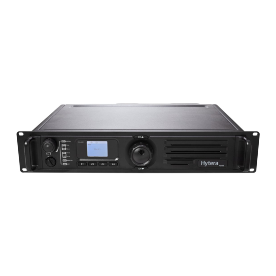
Page 5: Repeater Overview
Repeater Overview Front Panel Part Name Part Name Volume Control Knob / Power ○ ○ Accessory Jack Indicator ○ ○ Repeater Mode Indicator Analog Mode Indicator ○ ○ Slot 2 RX Indicator Slot 2 TX Indicator ○ ○ Digital Mode Indicator Slot 1 TX Indicator ○... -
Page 6: Rear Panel
Rear Panel Part Name Part Name ○ ○ TX Antenna Connector Optional Connector 1 ○ ○ RX/Duplex Antenna Connector Optional Connector 2 ○ ○ Monitor/Test Jack Accessory Jack ○ ○ DC Power Inlet Ethernet Port * ○ Ground Screw... -
Page 7: Internal Parts
Internal Parts Part Name Part Name ○ ○ Baseband Module Front Panel ○ ○ RF PA Module Excitor Module ○ RX Module Installation Proper installation can ensure optimum performance and reliability of the repeater. Be sure to read the following installation requirements and instructions carefully, before you install the repeater. -
Page 8: Installation Overview
Installation Overview The information below is an overview for installing the repeater and auxiliary equipment. Unpack and inspect the equipment. Perform a pre-installation function check test of the equipment, and configure parameters. Pay particular attention to environmental conditions at the site, ventilation ... -
Page 9: Installation Requirements
You may customize repeater parameters such as TX/RX frequency, TX power and signalling, according to user needs. After configuration of parameters is complete, you may perform site installation. Installation Requirements Environmental Conditions at Intended Installation Site The repeater may be installed in any location suitable for electronic communication equipment, provided that the environmental conditions do not exceed the equipment specifications for temperature, humidity and air quality. - Page 10 air to enter and exit. If several repeaters are installed in a single cabinet, ensure ventilation openings surrounding each repeater allow for adequate cooling. All cabinets must have at least 10cm of open space between the air vents and any ...
-
Page 11: Installation Steps
Ensure the antenna connector connected to the transmitter is beside the rear panel of the repeater. Take Hytera supplied duplexer as an example. If the transmitter is connected to the low cavity connector, the duplexer should be mounted with the front side facing upwards (see the following figure on the left);... - Page 12 Loosen the screw at the back of the top cover, and then pull the top cover to remove Loosen the 6 screws locking the PA heatsink, remove all power, data and RF cables from the PA, and finally remove the PA heatsink. Mount the duplexer, and fasten the 2 screws inside the housing and on the side panel respectively.
- Page 13 Ensure RF cables are properly connected between the duplexer and RF connectors. TX signal: Excitor module -> PA module -> Duplexer TX connector -> Duplexer antenna connector -> RX/duplex antenna connector (rear panel) RX signal: RX/duplex antenna connector (rear panel) -> Duplexer antenna connector -> Duplexer RX connector ->...
-
Page 14: Electrical Connections
Screws RF cables Screws Duplexer Mounted with Front Side Facing Downwards Electrical Connections After the repeater has been mechanically installed, electrical connections must be made. This involves making the following connections: DC power cord Antenna cables See the rear panel view for the positions of connectors. Power Supply Connections Ground Connection The repeater is equipped with a ground screw located on the rear panel. -
Page 15: Rf Antenna Connections
The repeater may be connected to a regulated DC power supply or a backup battery. The DC source or battery backup system is connected to the repeater through the DC power inlet at the rear of the repeater (see rear panel view). Caution: Before you make the connection, ensure the DC power supply or battery backup system is capable of supplying a minimum of 200W, and check if the DC power supply has current limit. -
Page 16: Post-Installation Checklist
Antenna Selection The selection of antenna is also critical to system performance. The selected antenna must be 50 Ohm impedance and capable of at least 50W. High gain antennas may be used to increase system coverage. Please take note of licensing restrictions when selecting high gain antennas. -
Page 17: Status Indications
Status Indications LCD Icons The LCD of your repeater displays the repeater status and menu items. The following are the icons that appear on the display. Standby Screen Status Icon (Tx power) Repeater Mode Channel Alias (programmable by dealer) Status Icons ... -
Page 18: Basic Operations
(RBM) Repeater transmitting (analog) repeater Slot 1 TX Indicator glows red transmitting on slot 1 (digital) Slot 1 TX Indicator flashes red Busy channel lockout * / transmission time-out * Slot 2 TX Indicator glows red Repeater transmitting on slot 2 (digital) Slot 2 TX Indicator flashes red Busy channel lockout * / transmission time-out * Slot 1 RX Indicator glows green... -
Page 19: Adjusting Power Level
volume adjustment through the knob is available. Adjusting Power Level You may request your dealer to set the TX power to high or low. The LCD displays icon for high power, and icon for low power. High power can optimize coverage of the repeater, to communicate with farther terminals. Backlight In insufficient light conditions, activating the backlight can illuminate the LCD and all the front panel keys, facilitating user operation. -
Page 20: Menu Navigation
Menu Navigation Radio Info Under this menu, you can view the basic information of your repeater, including serial number, radio model, frequency range, firmware version and etc. To access this menu: 1. In the home screen, press the Menu Navigation knob to enter the main menu. 2. -
Page 21: Channel Info
Channel Info Under this menu, you can view some information of the current channel, including channel alias, TX/RX frequency, channel spacing (analog only), TX/RX CTCSS/CDCSS (analog only), color code (digital only) and etc. To access this menu: 1. In the home screen, press the Menu Navigation knob to enter the main menu. 2. -
Page 22: Over Temperature Alarm
Over Temperature Alarm When temperature of the PA module exceeds the normal range, the Alarm Indicator will glow red and the LCD will display the prompt below: Then the repeater will disallow transmission, and you will need to: 1. Check if the surface temperature of PA heatsink exceeds 80℃. If yes, implement the following steps 2 and 3 to locate the failure. -
Page 23: Vswr Alarm
prompt below: Then the repeater will automatically switch to low TX power, to protect the transmitter from overheating. You will need to: 1. Check if the fan is blocked by any solid object. If yes, please remove it. 2. If you cannot solve the issue, please contact your local dealer for technical support. When the fan recovers normal operation, the LCD prompt will disappear, and the Alarm Indicator will go out. -
Page 24: Low Forward Power Alarm
result in poor transmitting performance, and even damage to the transmitter. 2. Check if connection between the transmitter and RF or antenna cables is loose or lost. If yes, please secure the connection or replace the cables. 3. If you cannot solve the issue, please contact your local dealer for technical support. When the VSWR falls within the normal range, the LCD prompt will disappear, and the Alarm Indicator will go out. - Page 25 Low Voltage Alarm Over Voltage Alarm Then the repeater will automatically shut off, but the LCD prompt will remain. You will need to: 1. Use a voltmeter to check if the input voltage of DC power supply is normal, especially if the voltage will run below the normal range while transmitting.
-
Page 26: Troubleshooting
Troubleshooting Phenomena Analysis Solution a. Properly connect the power cord a. Power cord is not connected or is and ensure secure connection. The repeater cannot not securely connected to the b. Check if the DC fuse has blown, be powered on. outlet. -
Page 27: Care And Cleaning
If the above solutions can not fix your problems, or you may have some other queries, please contact us or your local dealer for more technical support. Care and Cleaning To guarantee optimal performance as well as a long service life of your repeater, please follow the tips below. -
Page 28: Optional Accessories
Programming Cable (USB Port) SM10A1 * backup battery applicable) PC37 PS22002 Omni-directional Antenna Directional Antenna Note: Use the accessories specified by Hytera only. If not, Hytera shall not be liable for any losses or damages arising out of use of unauthorized accessories. - Page 29 The product is in conformity with the basic requirements of the applicable European directives. This is confirmed by the marking (CE) of the installed components. The Declarations of Conformity of the installed components may be viewed upon request. The product is assigned the equipment class code for radio equipment of class 2 (2.12) and is marked as follows. Within the scope of the European Directive 2014/53/EU, the network operator must ensure that the health and safety of the product user and other persons (Article 3 (1)a of 2014/53/EU and 1999/519/EC) are guaranteed.
- Page 30 This device complies with Part 15 of the FCC Rules. Operation is subject to the following two conditions: (1) this device may not cause harmful interference, and (2) this device must accept any interference received, including interference that may cause undesired operation. changes or modifications not expressly approved by the party responsible for compliance could void the user’s authority to operate the equipment.
Need help?
Do you have a question about the RD98XSVHFH and is the answer not in the manual?
Questions and answers