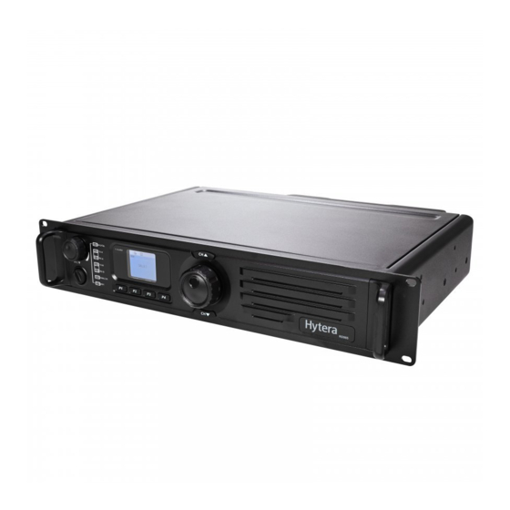
Hytera RD985 User Manual
Digital repeater
Hide thumbs
Also See for RD985:
- Owner's manual (27 pages) ,
- Owner's manual (21 pages) ,
- Service manual (333 pages)
Table of Contents
Advertisement
Quick Links
Advertisement
Table of Contents

Subscribe to Our Youtube Channel
Related Manuals for Hytera RD985


Summary of Contents for Hytera RD985
- Page 1 RD985 Digital Repeater User Manual...
- Page 3 Preface Thanks for your favor in our product. To derive optimum performance from the product, please read this manual and the supplied Safety Information Booklet carefully before use. This manual is applicable to the following model: RD98X (X may indicate 2, 5, 6 or 8)
- Page 4 Copyright Information Hytera is the trademark or registered trademark of Hytera Communications Co., Ltd. (the Company) in PRC and/or other countries or areas. The Company retains the ownership of its trademarks and product names. All other trademarks and/or product names that may be used in this manual are properties of their respective owners.
- Page 5 No part of this manual may be copied, modified, translated, or distributed in any manner without the express written permission of us. If you have any suggestions or would like to learn more details, please visit our website at: http://www.hytera.com/. RF Radiation Information RF Radiation Profile Radio Frequency (RF) is a frequency of electromagnetic radiation in the range at which radio signals are transmitted.
- Page 6 C95. 1-1992; Institute of Electrical and Electronic Engineers (IEEE) C95. 1 – 1999; International Commission on Non-Ionizing Radiation Protection (ICNIRP) 1998; FCC Regulations Federal Communication Commission (FCC) requires that all radio communication products should meet the requirements set forth in the above standards before they can be marketed in the U.S, and the manufacturer shall post a RF label on the product to inform users of operational instructions, so as to enhance their occupational health against exposure to RF energy.
-
Page 7: Table Of Contents
Contents Checking Items in the Package........................1 Product Overview ............................1 Front Panel ............................1 Programmable Keys * ........................... 2 Rear Panel ............................2 Internal Parts ............................3 Installation Guide ............................3 Installation Requirements ........................3 Before Installation ..........................4 Installation Steps ........................... - Page 8 Fan Failure Alarm ..........................14 VSWR Alarm ............................14 Low Forward Power Alarm ........................15 Over/Low Voltage Alarm ........................15 TX/RX Unlock Alarm ........................... 16 Troubleshooting ............................17 Care and Cleaning ............................. 18 Optional Accessories ..........................18...
-
Page 9: Checking Items In The Package
Checking Items in the Package Please unpack carefully and check that all items listed below are received. If any item is missing or damaged, please contact your dealer. Repeater Power Cord Documentation Kit Product Overview Front Panel Part Name Part Name Accessory Jack Slot 1 RX Indicator Volume... -
Page 10: Programmable Keys
Analog Mode Indicator LCD Display Slot 2 RX Indicator Channel Up (CH+) Slot 2 TX Indicator Navigation Knob Digital Mode Indicator Channel Down (CH-) Slot 1 TX Indicator Speaker Programmable Keys * For enhanced convenience, you can request your dealer to program the keys P1, P2, P3 and P4 as shortcuts to appropriate functions. -
Page 11: Internal Parts
Internal Parts Part Name Part Name Baseband Module Exciter Module Front Panel Receiver Module PA Module Installation Guide Proper installation can ensure optimum performance and reliability of the repeater. Therefore, be sure to read the following instructions before installation. Installation Requirements ... -
Page 12: Before Installation
spanner. Note: Please refer to Safety Information Booklet for more information. Before Installation Voltage Check Please check whether the voltage of DC power or battery meets the repeater specifications. Product Check Please check whether the repeater works properly by observing the 8 LEDs located in the front panel. Parameter Configuration When the repeater proves to work normally, configure appropriate parameters according to your actual requirements. - Page 13 Loosen the screw at the back of the top cover, and then pull the top cover to remove it. Loosen the 6 screws locking the PA heat sink, remove all power, data and RF cables from the PA, and finally remove the PA heat sink. See the figure below. Connect the RF cable.
-
Page 14: After-Installation Verification
RF Cable Screw Screw Duplexer with Front Side Facing Upwards RF Cable Screw Screw Duplexer with Front Side Facing Downwards After-installation Verification After installation is completed, power it on and verify whether it works properly by observing the 8 LEDs located in the front panel. -
Page 15: Led Indicator
Icon Name Icon Repeater Status More bars indicate better signal strength. RSSI Indicator Low TX power for the current channel. TX Power Indicator High TX power for the current channel. Scan Indicator Scan is in progress. Monitor Indicator The Monitor feature is active. Speaker Indicator The speaker is unmuted. -
Page 16: Basic Operations
Slot 2 RX Indicator glows The repeater is receiving on slot 2. green. Analog Mode Indicator The repeater is operating in Analog mode. glows yellow. Digital Mode Indicator glows The repeater is operating in Digital mode. blue. Basic Operations Turning the Repeater On/Off ON: To power up the repeater, connect a DC power supply to it. -
Page 17: Locking/Unlocking The Repeater
Enable: the backlight remains activated all the time. Note: When an alarm event occurs, the backlight will remain activated until the alarm disappears. Locking/Unlocking the Repeater You can request your dealer to lock the knob and all keys in the front panel to prevent accidental operation. -
Page 18: Radio Info
Radio Info Under this menu, you can view product information, including Radio ID, Radio Alias, Serial Number, Radio Model, Freq Range, Firmware Ver, RCDB Ver, Bootload Ver, Program Date and En Lang Ver. To access this menu: 1. In the home screen, press the Navigation knob to enter the main menu. 2. -
Page 19: Scan
Channel Type Channel Information Digital Channel CH Alias, TX Frequency, RX Frequency, Color Code CH Alias, TX Frequency, RX Frequency, CH Band, TX Analog Channel CTCSS/CDCSS, RX CTCSS/CDCSS CH Alias, TX Frequency, RX Frequency, CH Band, TX Mixed Channel CTCSS/CDCSS, RX CTCSS/CDCSS, Color Code To access this menu: 1. -
Page 20: Digital Speaker
In the above interface, you can enable or disable the Scan feature. To exit and return to the main menu, press the knob. Note: If the “Scan” option is not checked in the CPS by your dealer, you can not enable or disable the Scan feature via this menu. -
Page 21: Exit
Exit To exit the main menu: 1. In the main menu, rotate the Navigation knob to select the "Exit” option. Press this knob to return to the home screen. Alarm Information The repeater can automatically detect its operation status in real time. If the appropriate alarm indication option is checked in the CPS by your dealer, the LCD will give you a prompt message, and the Alarm Indicator will glow red in the case of a corresponding abnormality. -
Page 22: Fan Failure Alarm
4. If the above measures fail to solve the problem, contact your local dealer for technical support. When temperature falls into normal range, the prompt message will disappear, and the Alarm Indicator will go out. Fan Failure Alarm When the fan fails to work, the Alarm Indicator will glow red and the LCD will display the prompt message below: Then the repeater will automatically work at low TX power, to protect the transmitter from overheating. -
Page 23: Low Forward Power Alarm
mismatch and improper antenna could result in poor transmitting performance and even damage to the transmitter. If yes, please contact your local dealer to replace the antenna or reprogram your product. 2. Check if the connection between the transmitter and RF cable or antenna feed line is loose or damaged. -
Page 24: Tx/Rx Unlock Alarm
Low Voltage Alarm Over Voltage Alarm Then the repeater will automatically stop working. You need to: 1. Check whether the power voltage is too low or too high. If yes, replace the DC power supply or external battery. 2. Check whether the power cord is loose or damaged. If yes, secure or replace the cord. 3. -
Page 25: Troubleshooting
Caution: Disconnect the power supply before opening the chassis! Troubleshooting Phenomena Analysis Solution Properly connect the power cord Power cord is not connected or is The repeater and ensure secure connection. not securely connected to the outlet. cannot be Check if the fuse has blown. If powered on. -
Page 26: Care And Cleaning
If the above solutions can not fix your problems, or you may have some other queries, please contact us or your local dealer for more technical support. Care and Cleaning To guarantee optimal performance as well as a long service life of the product, please follow the tips below. - Page 27 Duplexer Bracket Palm Microphone Desktop Microphone BRK09 SM16A1 SM10A1 (for DT11 and DT14 only) External Power Supply (240W, Bracket (2U)(black) Bracket (2U)(grey) backup power supply applicable) BRK12 BRK14 PS22002 Power Cord (10A 12AWG) Fuse POA33 10-pin Programming Cable (USB) PWC11 PC37 Yagi Antenna Omni-directional Antenna...
- Page 28 Hytera Communications Corp,. Ltd Hytera Corp., Ltd. Hytera Corp,. Ltd. All Rights Reserved 9108 :518057 : - 4008307020 http://www .hytera . mco...
Need help?
Do you have a question about the RD985 and is the answer not in the manual?
Questions and answers