Table of Contents
Advertisement
Advertisement
Table of Contents

Related Manuals for Hytera RD98 Series


Summary of Contents for Hytera RD98 Series
- Page 2 Preface Thanks for your favor in our product. To derive optimum performance from the product, please read this manual and the supplied Safety Information Booklet carefully before use. This manual is applicable to the following model: RD98X (X may indicate 2, 5, 6 or 8)
- Page 3 U.S. Patent Numbers: #6,912,495 B2, #6,199,037 B1, #5,870,405, of a receiver in the absence of a suffi ciently strong desired input #5,826,222, #5,754,974, #5,701,390, #5,715,365, #5,649,050, signal. #5,630,011, #5,581,656, #5,517,511, #5,491,772, #5,247,579, Copyright Information #5,226,084 and #5,195,166. Hytera is the trademark or registered trademark of Hytera...
- Page 4 If you have any suggestions or would like to learn more details, occupational health against exposure to RF energy. please visit our website at: http://www.hytera.com. Operational Instructions and Training RF Radiation Information Guidelines RF Radiation Profi...
-
Page 5: Table Of Contents
Contents Checking Items in the Package ----------------------- 1 Alarm Information ----------------------------------------- 10 Product Overview ----------------------------------------- 1 Over Temperature Alarm --------------------------------- 10 Fan Failure Alarm ------------------------------------------ 10 Front Panel -------------------------------------------------- 1 VSWR Alarm ----------------------------------------------- 11 Programmable Keys * ------------------------------------- 1 Low Forward Power Alarm ------------------------------- 11 Rear Panel --------------------------------------------------- 2 Over/Low Voltage Alarm ---------------------------------- 11 Internal Parts ------------------------------------------------ 2... -
Page 6: Checking Items In The Package
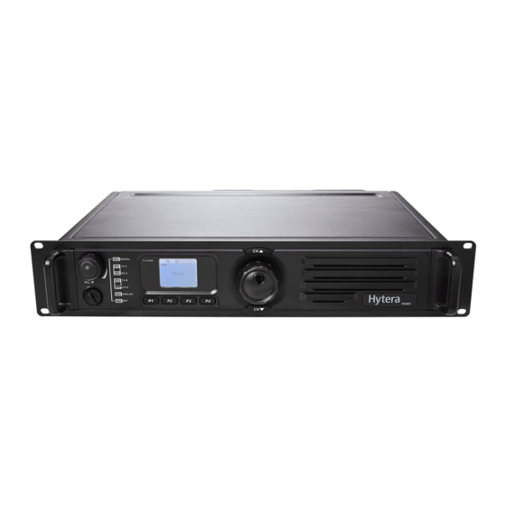
Checking Items in the Package Product Overview Please unpack carefully and check that all items listed below are Front Panel received. If any item is missing or damaged, please contact your dealer. Repeater Part Name Part Name Power Cord Vo l u m e C o n t r o l K n o b / Accessory Jack Power Indicator Repeater Mode Indicator... -
Page 7: Product Overview
Product Overview Rear Panel Internal Parts Part Name Part Name Part Name Part Name TX Antenna Interface Optional Interface 1 Baseband Module Exciter Module R X / D u p l e x A n t e n n a Front Panel Receiver Module Optional Interface 2... -
Page 8: Installation Guide
Installation Guide Proper installation can ensure optimum performance and reliability 3. Parameter Confi guration of the repeater. Therefore, be sure to read the following instructions When the repeater proves to work normally, confi gure appropriate before installation. parameters according to your actual requirements. And then you can proceed with on-site installation. - Page 9 Installation Guide 2. Install the duplexer onto the bracket. Be sure to observe the 4. Loosen the 6 screws locking the PA heat sink, remove all specifications of two antenna interfaces on the duplexer, to power, data and RF cables from the PA, and fi nally remove the determine which one should be connected to the transmitter.
-
Page 10: Installation Diagram
Installation Guide Installation Diagram Duplexer with Front Side Facing Downwards After-installation Verifi cation Duplexer with Front Side Facing Upwards After installation is completed, power it on and verify whether it works properly by observing the 8 LEDs located on the front panel. -
Page 11: Status Indication
Status Indication LCD Icon LED Indicator These icons may appear on LCD. They can help you easily identify LED Indicator Part No Repeater Status the repeater status. Power indicator glows Normal power-on green. Icon Name Icon Repeater Status Alarm indicator glows Abnormal operation More bars indicate better red. -
Page 12: Basic Operations
Basic Operations ● Timed: key press, knob operation or signal reception/ Turning the Repeater On/Off transmission can activate the backlight. If no foregoing event ● ON: To power up the repeater, connect a DC power supply to occurs within the specifi ed time period, the backlight will go out it. -
Page 13: Menu Navigation
Menu Navigation The options under the main menu vary with the channel type. Analog Channel Analog Channel ● In the above interface, you can rotate the Navigation Navigation knob to scroll through related information. To exit and return to the main menu, press the knob. -
Page 14: Scan
3. Press this knob again to view details, as shown below. In the above interface, you can enable or disable the Scan feature. To exit and return to the main menu, press the knob. Note: Note: If the “Scan” option is not checked in the CPS by your dealer, you can not enable or disable the Scan feature via this menu. -
Page 15: Alarm Information
Alarm Information The repeater can automatically detect its operation status in real 3. Check if connection between the transmitter and RF cable time. If the appropriate alarm indication option is checked in the or antenna feed line is loose or damaged. Poor connection CPS by your dealer, the LCD will give you a prompt message, and between them could cause high TX power, which would make the Alarm Indicator will glow red in the case of a corresponding... -
Page 16: Vswr Alarm
Alarm Information VSWR Alarm Low Forward Power Alarm High VSWR (voltage standing wave ratio) of TX antenna When the forward power is below the preset value, the Alarm connector could result in damage to the PA, and even failure of Indicator will glow red and the LCD will display the prompt the transmitter. -
Page 17: Tx/Rx Unlock Alarm
Alarm Information Low Voltage Over Voltage TX Unlock! RX Unlock! Alarm! Alarm! TX Unlock Alarm RX Unlock Alarm Low Voltage Alarm Over Voltage Alarm Then the repeater will automatically stop partial operations. You Then the repeater will automatically stop working. You need to: need to: 1. -
Page 18: Troubleshooting
Troubleshooting Phenomena Analysis Solution a. Properly connect the power cord and ensure a. Power cord is not connected or is not securely connected secure connection. T h e r e p e a t e r c a n n o t b e to the outlet. -
Page 19: Care And Cleaning
Care and Cleaning To guarantee optimal performance as well as a long service life of the product, please follow the tips below. Product Care Keep the product at a place of good ventilation and heat ● dissipation to facilitate normal work. Do not place irrelevant articles on top of the product to ensure ●... -
Page 20: Optional Accessories
Optional Accessories Optional Accessories The following items are the main optional accessories for the product, and please consult your local dealer for more information. Duplexer Bracket BRK09 Omni-directional Yagi Antenna Palm Microphone SM16A1 Desktop Microphone SM10A1 (for DT11 and DT14 only) Antenna External Power Supply (240W, backup Bracket (2U)(grey) - Page 21 Hytera Communications Corp., Ltd. 是海能达通信股份有限公司的商标或注册商标 2011 Hytera Corp., Ltd. All Rights Reserved. 2011 Hytera Corp., Ltd.版权所有 Address: HYT Tower, Hi-Tech Industrial Park North, Beihuan 地址:深圳市高新技术产业园北区北环路好易通大厦 RD., Nanshan District, Shenzhen, China 邮编:518057 Postcode:518057 服务热线:400-830-7020 http://www.hytera.com...
Need help?
Do you have a question about the RD98 Series and is the answer not in the manual?
Questions and answers