Table of Contents
Advertisement
Quick Links
Preface
Thank you for purchasing Hytera DMR Repeater. Combination of ergonomic design,
versatile digital functions and remarkable quality would refresh your experience and
enable you to be responsive to emergent situations.
To derive optimum performance from your product, please read this manual and the
supplied Safety Information Booklet carefully before use.
The manual is applicable to the following model:
RD98X
Advertisement
Table of Contents

Related Manuals for Hytera RD98X


Summary of Contents for Hytera RD98X
- Page 1 Preface Thank you for purchasing Hytera DMR Repeater. Combination of ergonomic design, versatile digital functions and remarkable quality would refresh your experience and enable you to be responsive to emergent situations. To derive optimum performance from your product, please read this manual and the supplied Safety Information Booklet carefully before use.
- Page 2 Hytera and HYT are trademarks or registered trademarks of Hytera Communications Co., Ltd. (“Hytera”) in PRC and/or other countries or areas. Hytera retains the ownership of its trademarks and product names. All other trademarks and/or product names that may be used in this manual are properties of their respective owners.
- Page 3 #5,491,772, #5,247,579, #5,226,084 and #5,195,166. Disclaimer Hytera endeavors to achieve the accuracy and completeness of this manual, but no warranty of accuracy or reliability is given. All the specifications and designs are subject to change without notice due to continuous technology development. No part of this manual may be copied, modified, translated, or distributed in any manner without the express written permission of Hytera.
- Page 4 U.S, and the manufacturer shall post a RF label on the product to inform users of operational instructions, so as to enhance their occupational health against exposure to RF energy. As a conscientious company centering on users, Hytera strictly complies with the forgoing requirements from design, production and test. EU Regulatory Conformance As certified by the qualified laboratory, the product is in compliance with the essential requirements and other relevant provisions of the Directive 1999/5/EC.
-
Page 5: Table Of Contents
Contents Checking Items in the Package ................... 5 Product Overview ........................ 6 Front Panel ........................6 Programmable Keys ..................... 6 Rear Panel ........................7 Internal Layout ......................8 Installation Guide ......................... 8 Installation Requirements ..................... 8 Before Installation ......................9 Installation Steps ...................... -
Page 6: Checking Items In The Package
Checking Items in the Package Please unpack carefully and check that all items listed below are received. If any item is missing or damaged, please contact your dealer. Power Cord Repeater Owner’s Manual Safety Information Booklet... -
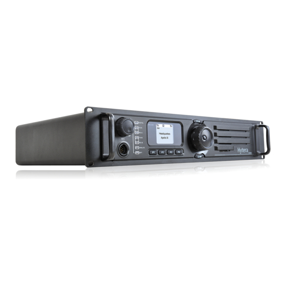
Page 7: Product Overview
Product Overview Front Panel Part Name Part Name ○ ○ Accessory Jack Volume Control Knob / Power Indicator ○ ○ Repeater Mode Indicator Analog Mode Indicator ○ ○ Slot 2 RX Indicator Slot 2 TX Indicator ○ ○ Digital Mode Indicator Slot 1 TX Indicator ○... -
Page 8: Rear Panel
Rear Panel Part Name Part Name ○ ○ TX Antenna Interface Optional Interface 1 RX/Duplex Antenna ○ ○ Optional Interface 2 Interface ○ ○ Monitor/Tuning Interface Accessory Jack ○ ○ Ethernet Port * DC Power Interface ○ Ground Screw... -
Page 9: Internal Layout
Internal Layout Part Name Part Name ○ ○ Baseband Module Front Panel ○ ○ PA Module Excitor Module ○ RX Module Installation Guide Proper installation can ensure optimum performance and reliability of the repeater. Therefore, be sure to read the following instructions before installation. Installation Requirements Installation Environment The repeater must be installed in a dry and well-ventilated place with ambient temperature... -
Page 10: Before Installation
The repeater can be installed in a rack, bracket and cabinet or on a desk. Installation Tool Tools required for installing the repeater include a cross head screwdriver, a torx screwdriver and a spanner. Note: please refer to Safety Information Booklet for more information. Before Installation Voltage Check Please check whether the voltage of DC power or... - Page 11 Install the duplexer onto the bracket. Be sure to observe the specifications of two antenna interfaces on the duplexer, to determine which one should be connected to the transmitter. The interface connecting the transmitter should be close to PA module to reduce RF loss, as shown below: Loosen the screw at the back of the top cover, and then pull the top cover to remove Loosen the 6 screws locking the PA heat sink, disconnect all power, data and RF cables, and finally remove the heat sink.
-
Page 12: Installation Diagram
After the duplexer is mounted properly, fasten it with the 2 screws inside the housing and on the side respectively. Then attach the PA heat sink and connect all cables. Installation Diagram RF Cable Screw Screw Duplexer with Front Side Facing Upwards... -
Page 13: After-Installation Verification
Screw RF Cable Screw Duplexer with Front Side Facing Downwards After-installation Verification After installation is completed, power it on and verify whether it works properly by observing the 8 LEDs located on the front panel. Status Indication LCD Icon These icons may appear on LCD. They can help you easily identify the repeater status. Icon Name Icon Repeater Status... -
Page 14: Led Indicator
Speaker Indicator The speaker is unmuted; * Alarm Indicator An alarm message appears; * The repeater is operating in DMO mode; * Operation Mode The repeater is operating in TMO mode; * Indicator The repeater is operating in Repeat mode; * LED Indicator LED Indicator Repeater Status... -
Page 15: Basic Operations
Basic Operations Turning the Repeater On/Off ON: turn on the repeater by connecting a DC power supply to it. During power-up process, the Power indicator glows green and the LCD shows animation. OFF: Disconnect the DC power supply. Adjusting Volume In analog mode: rotate the Volume Control knob clockwise to increase the volume or counter-clockwise to decrease the volume. -
Page 16: Locking/Unlocking The Repeater
disappears. Locking/Unlocking the Repeater You can request your dealer to lock the knob and all keys on the front panel to prevent accidental operation. To unlock, the repeater must be re-programmed by your dealer. Menu Navigation Radio Info Under this menu, you can rotate the Navigation knob to view product information, including Serial Number, Radio Model, Freq Range and Firmware Ver. -
Page 17: Channel Info
Just press the knob again. Channel Info Under this menu, you can rotate the Navigation knob to view channel information, including CH Alias, Tx Frequency, and so on. ◆To access this menu: 1. In the home screen, press the Navigation knob to enter the main menu. 2. -
Page 18: Over Temperature Alarm
Over Temperature Alarm When the temperature of PA module exceeds the normal range, the Alarm Indicator will glow red and the LCD will display the prompt message below: Then the repeater will stop transmitting, and you need to: 1. Check whether the temperature of heat sink surface is over 80℃. If yes, proceed with Step 2 and 3 to find out the cause. -
Page 19: Vswr Alarm
Then the repeater will automatically work at low TX power, to protect the transmitter from overheating. You need to: 1. Check whether the fan is blocked by an object. If yes, remove it. 2. If you cannot solve the problem, contact your local dealer for technical support. When the fan recovers normal operation, the prompt message will disappear, and the Alarm Indicator will go out. -
Page 20: Low Forward Power Alarm
2. Check if the connection between the transmitter and RF cable or antenna feeder is loose or damaged. If yes, secure or replace the cable or antenna feeder. 3. If you cannot solve the problem, contact your local dealer for technical support. When the VSWR falls within the normal range, the prompt message will disappear, and the Alarm Indicator will go out. - Page 21 Low Voltage Alarm Over Voltage Alarm Then the repeater will automatically stop working. You need to: 1. Check whether the power voltage is too low or too high. If yes, replace the DC power supply or externalbackup battery. 2. Check whether the power cord is loose or damaged. If yes, secure or replace the cord. 3.
-
Page 22: Troubleshooting
Troubleshooting Phenomena Analysis Solution a. Power cord is not connected a. Properly connect the power cord The repeater or is not securely connected and ensure secure connection. cannot be to the outlet. b. Check if the fuse has blown. If yes, powered on. -
Page 23: Care And Cleaning
connector and the cable, dealer to re-set the duplexer. or loss of connection c. Invisible damage of cable. d. Duplexer is not properly set (if the duplexer is mounted). If the above solutions can not fix your problems, or you may have some other queries, please contact us or your local dealer for more technical support. -
Page 24: Optional Accessories
SM10A1 * applicable) PS22002 Duplexer Bracket/Screws Omni-directional Antenna Directional Antenna (for DT11/DT12 only) Caution: Use the accessories specified by Hytera only. If not, Hytera shall not be liable for any losses or damages arising out of use of unauthorized accessories.
Need help?
Do you have a question about the RD98X and is the answer not in the manual?
Questions and answers