Hytera RD98X series User Manual
Dmr digital repeater
Hide thumbs
Also See for RD98X series:
- Manual manual (24 pages) ,
- Manual (24 pages) ,
- Upgrade manual (17 pages)
Table of Contents
Advertisement
Quick Links
Preface
Thank you for purchasing Hytera RD98X series DMR digital repeater.
As a product built to the DMR standard, RD98X is endowed with
ergonomic design, reliable performance and comprehensive digi-
tal functions to deliver an advanced communication solution. With
RD98X, you can make use of digital advantages to top the competi-
tion!
To ensure you get maximum benefit from the product, please read
this manual carefully before use.
Advertisement
Table of Contents

Related Manuals for Hytera RD98X series


Summary of Contents for Hytera RD98X series
- Page 1 Preface Thank you for purchasing Hytera RD98X series DMR digital repeater. As a product built to the DMR standard, RD98X is endowed with ergonomic design, reliable performance and comprehensive digi- tal functions to deliver an advanced communication solution. With RD98X, you can make use of digital advantages to top the competi-...
- Page 2 The following icons are available through this manual: to the purchaser with respect to Hytera computer programs. Any Hytera computer programs may not be copied, Caution: indicates situations that could cause modified, distributed, decompiled, or reverse-engineered in damage to your repeater or bodily injury.
- Page 3 Institute of Electrical and Electronic Engineers (IEEE) ● copied, modified, translated, or distributed in any manner C95. 1-1999 Edition without the express written permission of Hytera. International Commission on Non-Ionizing Radiation ● If you have any suggestions or would like to learn more Protection (ICNIRP) 1998 details, please visit us at: http://www.hytera.cn.
- Page 4 FCC Licensing Information FCC Licensing Requirements A license from Federal Communications Commission is Part 15 Compliance required prior to use. Your dealer will program each radio This equipment has been tested and found to comply with with your authorized frequencies, signaling codes, etc., and the limits for a Class B digital device, pursuant to part 15 will be there to meet your communications needs as your of the FCC Rules.
-
Page 5: Table Of Contents
Contents Checking Items in the Package ---------------- 1 Menu Navigation ----------------------------------- 13 Repeater Overview -------------------------------- 2 Radio Info -------------------------------------------- 13 Channel Info ----------------------------------------- 13 Front Panel ------------------------------------------ 2 Exit ----------------------------------------------------- 13 Rear Panel ------------------------------------------- 2 Alarm Information ---------------------------------- 14 Internal Parts ---------------------------------------- 3 Installation ------------------------------------------- 3 Over Temperature Alarm ------------------------- 14 Fan Failure Alarm ---------------------------------- 14... -
Page 6: Checking Items In The Package
Checking Items in the Package Please unpack carefully and check that all items listed below are received. If any item is missing or damaged, please contact your dealer. Repeater Duplexer Installation Kit Power Cord Owner’s Manual... -
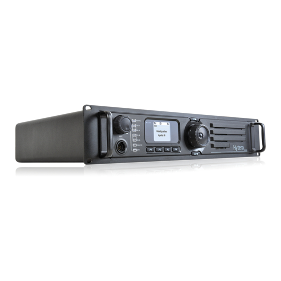
Page 7: Repeater Overview
Repeater Overview Front Panel Rear Panel No. Part Name No. Part Name No. Part Name No. Part Name TX Antenna Connector 2 Optional Connector 1 Analog Mode Indicator 2 Slot 2 RX Indicator RX/Duplex Antenna Optional Connector 2 Slot 2 TX Indicator Digital Mode Indicator Connector Slot 1 TX Indicator Slot 1 RX Indicator... -
Page 8: Internal Parts
Installation Repeater Overview Internal Parts Proper installation can ensure optimum performance and reliability of the repeater. Be sure to read the following installation requirements and instructions carefully, before you install the repeater. Installation Overview The information below is an overview for installing the repeater and auxiliary equipment. -
Page 9: Before Installation
Installation Before Installation Installation Requirements Before you install the repeater at the site, you are 1. Environmental Conditions at Intended Installation suggested to power on the repeater and check it for Site proper operation. The repeater may be installed in any location suitable for 1. - Page 10 Installation 3. Equipment Installation Methods Caution: If the repeater is to be installed in an area which is usually dusty, dirty, or does not meet the air The this repeater may be mounted in a rack, bracket or quality requirements, then the air used to cool the cabinet, and may be placed on your desk.
-
Page 11: Installation Steps
The installation steps are as follows: Take Hytera supplied duplexer as an example. If the 1. Mount the repeater in a rack, bracket or cabinet. transmitter is connected to the low cavity connector, 2. - Page 12 Installation 3. Loosen the screw at the back of the top cover, and TX signal: then pull the top cover to remove it. Excitor module -> PA module -> Duplexer TX connector -> Duplexer antenna connector -> RX/duplex antenna connector (rear panel) RX signal: RX/duplex antenna connector (rear panel) ->...
-
Page 13: Electrical Connections
Electrical Connections Installation After the repeater has been mechanically installed, Duplexer Mounted with Front Side Facing Downwards electrical connections must be made. This involves making the following connections: DC power cord ● Antenna cables ● See the rear panel view for the positions of connectors. Power Supply Connections 1. -
Page 14: Rf Antenna Connections
Electrical Connections 1. Duplexer Selection Caution: 1.Before you make the connection, ensure the DC The selection of duplexer is critical to system performance. power supply or battery backup system is capable of The use of a notch (band reject) duplexer is possible in supplying a minimum of 200W, and check if the DC some systems that are not located at high RF density power supply has current limit. -
Page 15: Post-Installation Checklist
Post-Installation Checklist Status Indications LCD Icons After the repeater has been mechanically installed and all electrical connections have been made, power may now The LCD of your repeater displays the repeater status and be applied and the repeater should be checked for proper menu items. -
Page 16: Led Indicator
Status Indications LED Indicator Slot 1 RX Indicator Repeater receiving (analog) / glows green repeater receiving on slot 1 (digital) LED Indicator Repeater Status Slot 1 RX Indicator Monitoring * Power Indicator Repeater being turned on flashes green glows green Slot 2 RX Indicator Repeater receiving on slot 2 Alarm Indicator glows Repeater giving an alarm due to... -
Page 17: Basic Operations
Basic Operations Turning the Repeater On/Off user operation. You dealer may set the backlight to operate in any of the Connect the repeater to a DC source to turn the repeater following modes: on. At this time, the Power Indicator glows green and the Timed: any key or knob operation or receiving/ ●... -
Page 18: Menu Navigation
Menu Navigation Channel Info Radio Info Under this menu, you can view some information of the current channel, including channel alias, TX/RX frequency, channel spacing (analog only), TX/RX CTCSS/CDCSS (analog only), color code (digital only) and etc. To access this menu: 1. -
Page 19: Alarm Information
Alarm Information The repeater can automatically detect its operation status 2. Check if ambient temperature and equipment ventilation in real time, such as PA over-temperature, low forward can satisfy the foregoing site installation requirements. power, high VSWR, high/low voltage and fan failure. When If not, please improve environmental conditions at the any of the above occurs, the LCD will give you a prompt, site as soon as possible, by mounting air conditioning... -
Page 20: Vswr Alarm
Alarm Information Then the repeater will automatically switch to low TX Then the repeater will automatically switch to low TX power, to protect the transmitter from overheating. power. You will need to: You will need to: 1. Check if the fan is blocked by any solid object. If yes, 1. -
Page 21: Low Forward Power Alarm
Alarm Information Low Forward Power Alarm Over/Low Voltage Alarm When the forward power is below the preset value, the When voltage is over or below the normal operating range Alarm Indicator will glow red and the LCD will display the (11V-15.6V) of the repeater, the Alarm Indicator will glow prompt below: red and the LCD will display the prompt below:... - Page 22 Alarm Information 3. If you cannot solve the issue, please contact your local dealer for technical support. Caution: If low voltage is detected when the repeater is powered by backup battery, you need to charge the battery with an external charger. Remove the battery from the repeater when charging.
-
Page 23: Troubleshooting
Troubleshooting Phenomena Analysis Solution The repeater cannot be a. Power cord is not connected or is not securely a. Properly connect the power cord and ensure powered on. connected to the outlet. secure connection. b. Power cord fuse is damaged. b. -
Page 24: Care And Cleaning
Care and Cleaning To guarantee optimal performance as well as a long service life of your repeater, please follow the tips below. Repeater Care Keep the repeater at a place of good ventilation and ● heat dissipation to facilitate normal work. Do not place irrelevant articles on top of the repeater ●... -
Page 25: Optional Accessories
PS22002 Programming Cable (USB Omni-directional Antenna Directional Antenna Port) PC37 Note: Use the accessories specified by Hytera only. If not, Hytera shall not be liable for any losses or damages arising out of use of unauthorized accessories.
Need help?
Do you have a question about the RD98X series and is the answer not in the manual?
Questions and answers