Table of Contents
Advertisement
Advertisement
Table of Contents

Related Manuals for Hytera RD982i


Summary of Contents for Hytera RD982i
- Page 1 USER MANUAL RD98 2i /RD98 2i- S/RD98 2i- S 100W DIGITAL REPEATER...
- Page 2 Preface Welcome to the world of Hytera and thank you for purchasing this product. This manual includes a description of the functions and step-by-step procedures for use. To avoid bodily injury or property loss caused by incorrect operation, please carefully read the Safety Information Booklet before use.
- Page 3 Copyright Information Hytera is the trademark or registered trademark of Hytera Communications Corporation Limited (the Company) in PRC and/or other countries or areas. The Company retains the ownership of its trademarks and product names. All other trademarks and/or product names that may be used in this manual are properties of their respective owners.
- Page 4 These standards consist of: United States Federal Communications Commission, Code of Federal Regulations; 47 CFR § 1.1307, 1.1310 and 2.1091 American National Standards Institute (ANSI) / Institute of Electrical and Electronic Engineers (IEEE) C95. 1:2005; Canada RSS102 Issue 5 March 2015 ...
- Page 5 manufacturer shall post a RF label on the product to inform users of operational instructions, so as to enhance their occupational health against exposure to RF energy. Operational Instructions and Training Guidelines To ensure optimal performance and compliance with the occupational/controlled environment RF energy exposure limits in the above standards and guidelines, users should always adhere to the followings: ...
- Page 6 Documentation Information Icon Conventions Icon Description Indicates references that can further describe the related topics. Indicates situations that could cause data loss or equipment damage. Notational Conventions Item Description Example To save the configuration, click Apply. Denotes menus, tabs, parameter Boldface names, window...
- Page 7 Operation Description Short press Press and release quickly. Long press Press and hold for the preset duration. Press and hold Keep the key pressed.
-
Page 8: Table Of Contents
Contents 1. Packing List ............................2 2. Product Overview ..........................3 2.1 Front Panel ............................3 2.2 Rear Panel ............................4 2.3 Internal Parts ............................. 5 3. Installation ............................. 6 3.1 Installation Requirements ........................6 3.2 Installation Procedure ........................6 3.2.1 Installing the Duplexer (Optional) .................... -
Page 9: Packing List
1. Packing List Please unpack carefully and check that you have received the following items. If any item is missing or damaged, please contact your dealer. Item Quantity (PCS) Item Quantity (PCS) Repeater Documentation Kit DC Power Cord Figures in this manual are for reference only. ... -
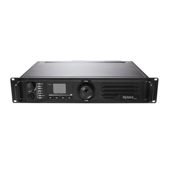
Page 10: Product Overview
2. Product Overview 2.1 Front Panel Part Name Part Name Accessory Jack Timeslot 1 RX Indicator Volume Control Knob/Power Indicator Alarm Indicator Operation Status Indicator Programmable Keys Analog Mode Indicator LCD Display Timeslot 2 RX Indicator Channel Up Key Timeslot 2 TX Indicator Navigation Knob Digital Mode Indicator Channel Down Key... -
Page 11: Rear Panel
2.2 Rear Panel Part Name Part Name TX Antenna Connector (Type-N Female) Accessory Jack Optional Interface 1 DC Power Inlet RX/Duplex Antenna Connector (Type-N Ethernet Port Female) Optional Interface 2 Ground Screw Monitor/Tuning Interface... -
Page 12: Internal Parts
2.3 Internal Parts Part Name Part Name Baseband Module Exciter Module Front Panel Receiver Module PA Module... -
Page 13: Installation
3. Installation To ensure optimum performance and reliability of the product, install it properly according to the following instructions. 3.1 Installation Requirements Ensure the following requirements are met: Environment: a dry and well-ventilated place with ambient temperature of -30°C to +60°C and relative humidity of 95% ... - Page 14 Duplexer with front side facing downwards Loosen the three screws on the bracket with a Phillips screwdriver.
- Page 15 2. Install the duplexer onto the bracket. Observe the specifications of the two antenna interfaces on the duplexer to determine which one should be connected to the repeater. The interface connecting the repeater should be close to PA module to reduce RF loss. Loosen the screws at the back of the repeater top cover, and then pull the top cover backwards to remove it.
-
Page 16: Installing The Repeater
Connect the RF cable through the hole next to the PA module. Install the duplexer to the repeater. Mount the duplexer on the exciter module and receiver module of the repeater, and then fasten the duplexer with the two screws inside the housing and the two screws on the side of the housing. Attach the PA module and connect all PA power, data and RF cables to it. -
Page 17: Basic Operations
4. Basic Operations 4.1 Turning the Repeater On or Off To turn on the repeater, connect it to the DC power supply. During power-up process, the Power Indicator glows green and the power-up screen appears. To turn off the repeater, disconnect it from the DC power supply. 4.2 Adjusting the Volume ... -
Page 18: Locking Or Unlocking The Repeater
When an error occurs, the backlight glows until the alarm disappears. Then the backlight recovers the original mode. 4.5 Locking or Unlocking the Repeater You can request your dealer to lock the knob and all keys in the front panel to prevent accidental operation. -
Page 19: Status Indications
5. Status Indications 5.1 Checking LCD Indications Icon Description Low TX power for the current channel. High TX power for the current channel. An accessory is connected. An alarm message is given. The GPS signals do not synchronize with the satellite signals. The GPS signals synchronize with the satellite signals. -
Page 20: Checking Led Indications
5.2 Checking LED Indications Indicator Color Description Power Indicator Green Normal power-on. Alarm Indicator Abnormal operation and the alarm pops up. Green The repeater is operating in Repeater mode. Operation Status Indicator The repeater is operating in Base mode. Digital Mode Indicator Blue The repeater is operating in Digital mode. -
Page 21: Alarm Information
6. Alarm Information With the Alarm feature enabled by your dealer, the repeater can detect alarms. When an error occurs, the LCD displays the alarm message with the Alarm Indicator on the front panel glowing red. 6.1 Low Forward Power Alarm Description When the forward power is below the preset value, the Alarm Indicator glows red and the LCD displays the message below:... -
Page 22: Tx/Rx Unlock Alarm
6.2 TX/RX Unlock Alarm Description When the TX PLL or RX PLL is unlocked, the Alarm Indicator glows red and the LCD displays the message below: TX Unlock Alarm RX Unlock Alarm Then certain features of the repeater become unavailable automatically. Solution Disconnect the power supply, and then open the chassis to check if any cable is loose or damaged. -
Page 23: Over Temperature Alarm
Then the repeater will automatically work at low TX power to avoid overheating. Solution Check whether the fan is blocked by an object. If yes, remove the object. If no, contact your local dealer for technical support. After the fan recovers the normal operation, the message disappears, and the Alarm Indicator goes off. 6.4 Over Temperature Alarm Description When the temperature of the PA module exceeds the normal range, the Alarm Indicator glows red and... -
Page 24: Over/Low Voltage Alarm
Do not touch the surface of the PA module to avoid burn. You can use a digital thermometer with thermocouple to measure the temperature value. Check whether the ambient temperature and ventilation conditions of the repeater satisfy the foregoing installation requirements. ... - Page 25 Check whether the DC power cord is loose or damaged. If yes, secure or replace the cord. If no, contact your local dealer for technical support.
-
Page 26: Voltage Standing Wave Ratio (Vswr) Alarm
6.6 Voltage Standing Wave Ratio (VSWR) Alarm Description When the repeater detects that the voltage standing wave ratio (VSWR) of the TX antenna for the PA module exceeds the normal value, the Alarm Indicator glows red and the LCD displays the message below: Then the repeater will automatically work at low TX power. -
Page 27: Troubleshooting
6. Troubleshooting Phenomena Analysis Solution power cord Properly connect the power cord and unconnected securely ensure secure connection. connected to the outlet. Power-on Failure. The fuse in the power cord may be Check if the fuse has blown. If yes, damaged. - Page 28 If the above solutions cannot fix the problems for you, or you may have some other queries, please contact us or your local dealer for more technical support.
-
Page 29: Care And Cleaning
7. Care and Cleaning To guarantee optimal performance as well as a long service life of the product, please follow the tips below. 7.1 Product Care Keep the product at a place of good ventilation and heat dissipation to facilitate normal work. ... -
Page 30: Optional Accessories
8. Optional Accessories Use the accessories specified by the Company only. If not, Hytera shall not be liable for any losses or damages arising out of use of unauthorized accessories. For more information of the main optional accessories for the repeater, please consult your local dealer. - Page 31 Hytera Communications Corporation Limited. 2018 Hytera Communications Corporation Limited. Address: Hytera Tower,Hi-Tech Industrial Park North,9108#Beihuan Road, Nanshan District,Shenzhen,People’s Republic of China...
Need help?
Do you have a question about the RD982i and is the answer not in the manual?
Questions and answers