Table of Contents
Advertisement
Quick Links
This user's guide describes the operation of the evaluation module ( TPA3245EVM, rev. B) for the
TPA3245 100-W Stereo/200-W mono PurePath™ Ultra-HD Analog Input Power Stage. The user's guide
also provides design information, which includes schematic, BOM, and PCB layout. For questions and
support, go to the E2E forums (e2e.ti.com).
The main contents of this document are:
•
Hardware descriptions and implementation
•
Design information
Related documents:
•
TPA3245 data sheet (SLASEC7)
spacer
1
1.1
1.2
1.3
1.4
2
2.1
TPA3245EVM Setup
2.2
2.3
3
3.1
3.2
3.3
4
5
5.1
5.2
5.3
5.4
1
2
3
4
5
6
TPA3245EVM Board Dimension
7
8
9
TPA3245EVM Schematic 3
PurePath is a trademark of Texas Instruments.
SLVUAT6 - September 2016
Submit Documentation Feedback
..........................................................................................................
............................................................................................
.................................................................................
........................................................................................................
...............................................................................................
...........................................................................................
...............................................................................
................................................................................
....................................................................................
..........................................................................................................
...................................................................................
................................................................................
....................................................................................................
........................................................................................
................................................................................................................
................................................................................................
...............................................................................
.........................................................................................
...............................................................................................
...............................................................................................
...............................................................................................
Copyright © 2016, Texas Instruments Incorporated
TPA3245 Evaluation Module
Contents
............................................................
....................................................
...........................................................
....................................................................
.......................................................................
List of Figures
................................................
...........................................................................
User's Guide
SLVUAT6 - September 2016
TPA3245 Evaluation Module
3
3
4
4
5
6
6
6
7
8
8
10
11
12
13
13
15
16
19
3
6
12
13
14
15
19
20
21
1
Advertisement
Table of Contents

Related Manuals for Texas Instruments TPA3245


Summary of Contents for Texas Instruments TPA3245
-
Page 1: Table Of Contents
This user’s guide describes the operation of the evaluation module ( TPA3245EVM, rev. B) for the TPA3245 100-W Stereo/200-W mono PurePath™ Ultra-HD Analog Input Power Stage. The user’s guide also provides design information, which includes schematic, BOM, and PCB layout. For questions and support, go to the E2E forums (e2e.ti.com). - Page 2 Mode Selection Pins ..................SE + 1 BTL Default Jumper States ..................... PBTL Default Jumper States .................... SE 4.0 Default Jumper States ......................Bill of Materials TPA3245 Evaluation Module SLVUAT6 – September 2016 Submit Documentation Feedback Copyright © 2016, Texas Instruments Incorporated...
-
Page 3: Hardware Overview
Hardware Overview The TPA3245EVM PurePath™ Ultra-HD evaluation module demonstrates the TPA3245DDV integrated circuit from Texas Instruments. The TPA3245DDV is a high-performance, high-power, class-D amplifier that enables true premium sound quality with high-efficiency class-D technology. It features an advance integrated feedback design and high-speed gate driver error correction (PurePath Ultra-HD), which enables ultra-low distortion across the audio band and superior audio quality. -
Page 4: Tpa3245Evm Frequency Adjust
For differential input operation, J4 or J19 jumpers are set to the DIFF position, and the TPA3245EVM uses the NE5532 to buffer the differential input signal to the differential inputs of the TPA3245. The input RCA jack, J3, is used to provide INA, RCA jack J14 provides INB, RCA jack J18 provides INC, and RCA jack J15 provides IND with differential inputs. -
Page 5: Tpa3245Evm Clip Overtemperature And Fault Indicators
TPA3245EVM Clip Overtemperature and Fault Indicators The TPA3245EVM is equipped with LED indicators that illuminate when the FAULT or CLIP_OTW pin goes low. See Table 2 and the TPA3245 data sheet (SLASEC7) for more details. Table 2. Fault and Clip Overtemperature Status FAULT CLIP_OTW Description Overtemperature (OTE) or overload (OLP) or undervoltage (UVP). -
Page 6: Tpa3245Evm Setup
• Two 2–8 Ω (approximately 200 W) speaker and resistor loads • Four speaker/banana cables • RCA input cables • Analog output audio source TPA3245 Evaluation Module SLVUAT6 – September 2016 Submit Documentation Feedback Copyright © 2016, Texas Instruments Incorporated... -
Page 7: Hardware Default Setup Btl (2.0)
Using a smart phone, tablet, or PC with headphone to RCA cable, audio streaming via headphone jack can begin once the EVM is powered up correctly with jumpers in their default state. Start the media player of your choice and enjoy the enhanced audio performance TPA3245 provides as a quick check of the setup. -
Page 8: Using The Tpa3245Evm In Different Output Configurations
OUTB. • Set J19 jumper position to DIFF. • Connect left (stereo) channel input to female RCA jack input C/CD (WHITE) for OUTC speaker. TPA3245 Evaluation Module SLVUAT6 – September 2016 Submit Documentation Feedback Copyright © 2016, Texas Instruments Incorporated... - Page 9 DIFF. NOTE: OUTC and OUTD are the single-ended output channels and OUTA and OUTB are the BTL channel for 2.1 operations. SLVUAT6 – September 2016 TPA3245 Evaluation Module Submit Documentation Feedback Copyright © 2016, Texas Instruments Incorporated...
-
Page 10: Pbtl (0.1) Output Operation
RCA male jack to female RCA jack input B (YELLOW) and set J4 jumper position to DIFF. NOTE: INA and INB are the inputs for PBTL and INC and IND are grounded for PBTL operation. TPA3245 Evaluation Module SLVUAT6 – September 2016 Submit Documentation Feedback Copyright © 2016, Texas Instruments Incorporated... -
Page 11: Single-Ended (Se) Output (4.0) Operation
• Connect input to female RCA jack input D (BLACK) for OUTD speaker. NOTE: The performance of the TPA3245EVM/TPA3245 is dependent on the power supply. Design the power supply with margins that can deliver the needed power. In low-frequency applications, additional bulk capacitance may be needed. Replacing the bulk capacitors on the TPA3245EVM with more capacitance may be necessary, depending on the power supply used. -
Page 12: Optional Inductors
UA8014-AL 10 PH Dual Inductor 0.01 0.001 0.01 Watts D001 Figure 3. TPA3245EVM THD + N vs Output Power 30 V, BTL 4 Ω, 600 kHz TPA3245 Evaluation Module SLVUAT6 – September 2016 Submit Documentation Feedback Copyright © 2016, Texas Instruments Incorporated... -
Page 13: Board Layouts, Bill Of Materials, And Schematic
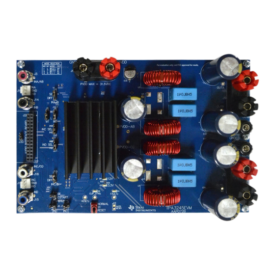
Board Layouts, Bill of Materials, and Schematic TPA3245EVM Board Layouts Figure 4 Figure 5 illustrate the board layouts for the EVM. Figure 4. TPA3245EVM Top Composite Assembly SLVUAT6 – September 2016 TPA3245 Evaluation Module Submit Documentation Feedback Copyright © 2016, Texas Instruments Incorporated... -
Page 14: Tpa3245Evm Bottom Composite Assembly
Board Layouts, Bill of Materials, and Schematic www.ti.com Figure 5. TPA3245EVM Bottom Composite Assembly TPA3245 Evaluation Module SLVUAT6 – September 2016 Submit Documentation Feedback Copyright © 2016, Texas Instruments Incorporated... -
Page 15: Tpa3245Evm Board Dimension
Figure 6 illustrates the TPA3245EVM board dimensions 180 mm × 120 mm (image represented here is not actual size). Figure 6. TPA3245EVM Board Dimension SLVUAT6 – September 2016 TPA3245 Evaluation Module Submit Documentation Feedback Copyright © 2016, Texas Instruments Incorporated... -
Page 16: Bill Of Materials
Lite-On D5, D6 Green LED, Green, SMD LED_0805 LTST-C171GKT Lite-On HEATSINK TI TAS5612 AND TAS5614 HEATSINK TI TAS5612 AND ATS-TI1OP-563-C1-R0 Advanced Thermal Solutions TAS5614 TPA3245 Evaluation Module SLVUAT6 – September 2016 Submit Documentation Feedback Copyright © 2016, Texas Instruments Incorporated... - Page 17 R24, R28 RES, 47 k, 5%, 0.1 W, 0603 0603 RC0603JR-0747KL Yageo America 3.30k RES, 3.30 k, 1%, 0.1 W, 0603 0603 RC0603FR-073K3L Yageo America SLVUAT6 – September 2016 TPA3245 Evaluation Module Submit Documentation Feedback Copyright © 2016, Texas Instruments Incorporated...
- Page 18 TP13, TP14 TP15, TP16, TP17, Testpoint Test Point, 0.45mm hole size TP_H0.45P0.75 Texas Instruments TP18, TP19, TP20, TP21, TP22, TP23, TP24, TP25, TP26, TP27, TP28 TPA3245 Evaluation Module SLVUAT6 – September 2016 Submit Documentation Feedback Copyright © 2016, Texas Instruments Incorporated...
-
Page 19: Tpa3245Evm Schematic
10µF 10µF 0.1uF 0.1uF <- ROUTED GROUND TO AGND ON DUT (Pins 12/13) Copyright © 2016, Texas Instruments Incorporated Figure 7. TPA3245EVM Schematic 1 SLVUAT6 – September 2016 TPA3245 Evaluation Module Submit Documentation Feedback Copyright © 2016, Texas Instruments Incorporated... -
Page 20: Tpa3245Evm Schematic 2
FAULT FAULT CLIP_OTW FAULT Orange RESET-SW 1µF 0.1uF MONITORS 3.30k TPS3802K33DCKR 0.1uF RESET Copyright © 2016, Texas Instruments Incorporated Figure 8. TPA3245EVM Schematic 2 TPA3245 Evaluation Module SLVUAT6 – September 2016 Submit Documentation Feedback Copyright © 2016, Texas Instruments Incorporated... - Page 21 LM2940IMP-12/NOPB 0.1uF 3.3V Green 3.3V +12V 3.3V OUTPUT OUTPUT 10µF 100µF TLV1117-33IDCY 3.3V Copyright © 2016, Texas Instruments Incorporated Figure 9. TPA3245EVM Schematic 3 SLVUAT6 – September 2016 TPA3245 Evaluation Module Submit Documentation Feedback Copyright © 2016, Texas Instruments Incorporated...
- Page 22 STANDARD TERMS AND CONDITIONS FOR EVALUATION MODULES Delivery: TI delivers TI evaluation boards, kits, or modules, including demonstration software, components, and/or documentation which may be provided together or separately (collectively, an “EVM” or “EVMs”) to the User (“User”) in accordance with the terms and conditions set forth herein.
- Page 23 FCC Interference Statement for Class B EVM devices NOTE: This equipment has been tested and found to comply with the limits for a Class B digital device, pursuant to part 15 of the FCC Rules. These limits are designed to provide reasonable protection against harmful interference in a residential installation.
- Page 24 【無線電波を送信する製品の開発キットをお使いになる際の注意事項】 開発キットの中には技術基準適合証明を受けて いないものがあります。 技術適合証明を受けていないもののご使用に際しては、電波法遵守のため、以下のいずれかの 措置を取っていただく必要がありますのでご注意ください。 1. 電波法施行規則第6条第1項第1号に基づく平成18年3月28日総務省告示第173号で定められた電波暗室等の試験設備でご使用 いただく。 2. 実験局の免許を取得後ご使用いただく。 3. 技術基準適合証明を取得後ご使用いただく。 なお、本製品は、上記の「ご使用にあたっての注意」を譲渡先、移転先に通知しない限り、譲渡、移転できないものとします。 上記を遵守頂けない場合は、電波法の罰則が適用される可能性があることをご留意ください。 日本テキサス・イ ンスツルメンツ株式会社 東京都新宿区西新宿6丁目24番1号 西新宿三井ビル 3.3.3 Notice for EVMs for Power Line Communication: Please see http://www.tij.co.jp/lsds/ti_ja/general/eStore/notice_02.page 電力線搬送波通信についての開発キットをお使いになる際の注意事項については、次のところをご覧ください。http:/ /www.tij.co.jp/lsds/ti_ja/general/eStore/notice_02.page SPACER EVM Use Restrictions and Warnings: 4.1 EVMS ARE NOT FOR USE IN FUNCTIONAL SAFETY AND/OR SAFETY CRITICAL EVALUATIONS, INCLUDING BUT NOT LIMITED TO EVALUATIONS OF LIFE SUPPORT APPLICATIONS.
- Page 25 Notwithstanding the foregoing, any judgment may be enforced in any United States or foreign court, and TI may seek injunctive relief in any United States or foreign court. Mailing Address: Texas Instruments, Post Office Box 655303, Dallas, Texas 75265 Copyright © 2016, Texas Instruments Incorporated...
- Page 26 IMPORTANT NOTICE Texas Instruments Incorporated and its subsidiaries (TI) reserve the right to make corrections, enhancements, improvements and other changes to its semiconductor products and services per JESD46, latest issue, and to discontinue any product or service per JESD48, latest issue.
Need help?
Do you have a question about the TPA3245 and is the answer not in the manual?
Questions and answers