Table of Contents
Advertisement
Quick Links
This user's guide describes the characteristics, operation, and use of the TPA3220 evaluation module. A
complete printed-circuit board (PCB) description, schematic diagram, and bill of materials (BOM) are also
included.
SLAU754A – January 2018 – Revised August 2019
Submit Documentation Feedback
TPA3220 Evaluation Module
Copyright © 2018–2019, Texas Instruments Incorporated
SLAU754A – January 2018 – Revised August 2019
TPA3220 Evaluation Module
User's Guide
1
Advertisement
Table of Contents

Subscribe to Our Youtube Channel
Related Manuals for Texas Instruments TPA3220EVM


Summary of Contents for Texas Instruments TPA3220EVM
- Page 1 This user's guide describes the characteristics, operation, and use of the TPA3220 evaluation module. A complete printed-circuit board (PCB) description, schematic diagram, and bill of materials (BOM) are also included. SLAU754A – January 2018 – Revised August 2019 TPA3220 Evaluation Module Submit Documentation Feedback Copyright © 2018–2019, Texas Instruments Incorporated...
-
Page 2: Table Of Contents
Output Mode and Modulation Mode Selection ....................Power Supply Summary ....................AIB Connector (J28) Pinout .................... AIB Power Rail Specifications ................... TPA3220EVM Bill of Materials TPA3220 Evaluation Module SLAU754A – January 2018 – Revised August 2019 Submit Documentation Feedback Copyright © 2018–2019, Texas Instruments Incorporated... -
Page 3: Quick Start (Btl Mode)
• Four speaker, banana cables • Four XLR or two RCA input cables • Analog output audio source SLAU754A – January 2018 – Revised August 2019 TPA3220 Evaluation Module Submit Documentation Feedback Copyright © 2018–2019, Texas Instruments Incorporated... -
Page 4: Connections And Board Configuration (Btl Mode)
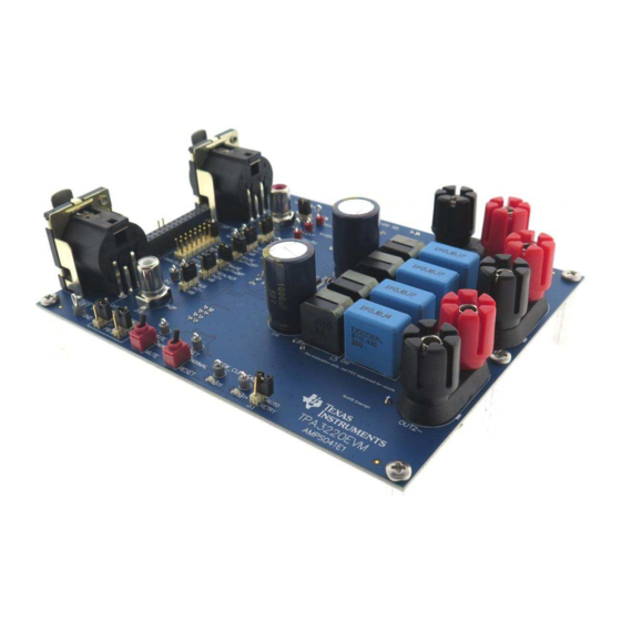
Figure 2 Figure 3 show the EVM board. Figure 2. EVM Board (Top Side) Figure 3. EVM Board (Bottom Side) TPA3220 Evaluation Module SLAU754A – January 2018 – Revised August 2019 Submit Documentation Feedback Copyright © 2018–2019, Texas Instruments Incorporated... -
Page 5: Jumper And Switch Configurations (Btl Mode)
1. Ensure the power supply is OFF. Connect the power supply positive terminal to J1 PVDD (red) and negative terminal to J1 GND (black). 2. Connect the left channel speaker, power resistor load (3–8 Ω) to the TPA3220EVM positive output terminal (J9 OUT1+ (red)) and other side of the speaker, power resistor to the TPA3220EVM negative output terminal (J9 OUT1–... -
Page 6: Power-Up
Power-Up Ensure that required connections and configurations have been checked. The TPA3220EVM board can now be powered on. 1. Enable the power supply from 12 V to 30 V and ensure that LED D5 illuminates. LEDs D2 and D4 should not be illuminated. -
Page 7: Setup By Mode
PBTL mode output configuration with 4 inductors. OUT-A OUT-B Class-D Amplifier OUT-C OUT-D Figure 4. Output Configuration PBTL - 4 Inductors SLAU754A – January 2018 – Revised August 2019 TPA3220 Evaluation Module Submit Documentation Feedback Copyright © 2018–2019, Texas Instruments Incorporated... -
Page 8: Evm Board With Connectors And Jumpers
1. Ensure the power supply is OFF. Connect power supply positive terminal to J1 PVDD (red) and negative terminal to J1 GND (black). 2. Connect one speaker, power resistor load (2–8 Ω) to TPA3220EVM positive output terminal (J9 OUT1+ (red)) and other side of speaker, power resistor to TPA3220EVM negative output terminal (J9 OUT1–... -
Page 9: Jumper And Switch Configurations (Pbtl Mode)
2.2.2 Power-Up Ensure that required connections and configurations have been checked. The TPA3220EVM board can now be powered on. 1. Enable the power supply from 12 V to 30 V and ensure that LED D5 illuminates. LEDs D2 and D4 should not be illuminated. -
Page 10: Hardware Configuration
Hardware Configuration www.ti.com Hardware Configuration Indicator Overview (OTW_CLIP and FAULT) The TPA3220EVM is equipped with LED indicators that illuminate when the FAULT or OTW_CLIP pin goes low. See Table 3 TPA3220 100-W Peak HD-Audio, Analog-Input, Class-D for more details. Table 3. Fault and Clip Overtemperature Status... -
Page 11: Modulation Modes (Ad Mode And Head Mode)
Modulation Modes (AD Mode and HEAD Mode) The TPA3220EVM supports both AD modulation as well as HEAD modulation. In AD mode, each of the two half-bridge outputs are continuously switching. AD mode is the default mode for the TPA3220EVM. -
Page 12: Evm Power Tree
Hardware Configuration www.ti.com EVM Power Tree The TPA3220EVM includes a few options for power configuration so that various input types can be evaluated. 3.6.1 TPA3220 Supplies The TPA3220 device has a few power supplies which each have their own voltage range and rules. -
Page 13: Lc Response And Overview
BTL common mode with values of 10 µH and 1 µF for the filter. This tool is also helpful when designing a different board featuring one of TI’s class-D amplifiers. SLAU754A – January 2018 – Revised August 2019 TPA3220 Evaluation Module Submit Documentation Feedback Copyright © 2018–2019, Texas Instruments Incorporated... -
Page 14: Reset Circuit And Por
Reset Circuit and POR The TPA3220EVM includes RESET supervision so that the TPA3220 device will remain in reset until all power rails are up and stable. The RESET supervisor also ensures that the device will be put into reset if one of the power rails experiences a brown out. -
Page 15: Aib Connector (J28) Pinout
Source PVDD 15–80 V 500 mA External Source 12 V 12 V 500 mA 3.3 V 3.3 V 100 mA SLAU754A – January 2018 – Revised August 2019 TPA3220 Evaluation Module Submit Documentation Feedback Copyright © 2018–2019, Texas Instruments Incorporated... -
Page 16: Evm Design Documents
This section contains the EVM board layouts, schematics, and bill of materials (BOM). TPA3220 Board Layouts Figure 9 Figure 10 illustrate the EVM board layouts. Figure 9. TPA3220 EVM Top Composite Assembly TPA3220 Evaluation Module SLAU754A – January 2018 – Revised August 2019 Submit Documentation Feedback Copyright © 2018–2019, Texas Instruments Incorporated... -
Page 17: Tpa3220 Evm Bottom Composite Assembly
EVM Design Documents www.ti.com Figure 10. TPA3220 EVM Bottom Composite Assembly SLAU754A – January 2018 – Revised August 2019 TPA3220 Evaluation Module Submit Documentation Feedback Copyright © 2018–2019, Texas Instruments Incorporated... -
Page 18: Tpa3220 Board Layouts
EVM Design Documents www.ti.com TPA3220 Board Layouts Figure 11 shows the EVM board dimensions. Figure 11. TPA3220 EVM Board Dimensions TPA3220 Evaluation Module SLAU754A – January 2018 – Revised August 2019 Submit Documentation Feedback Copyright © 2018–2019, Texas Instruments Incorporated... -
Page 19: Tpa3220 Evm Schematics
IN2-_AIB 1µF AUGNDR IN2- IN2 SE 5V-PU IN2M Copyright © 2017, Texas Instruments Incorporated Figure 12. TPA3220 EVM Schematic 1 SLAU754A – January 2018 – Revised August 2019 TPA3220 Evaluation Module Submit Documentation Feedback Copyright © 2018–2019, Texas Instruments Incorporated... -
Page 20: Tpa3220 Evm Schematic 2
OTW_CLIP RESET Orange RESET-SW MONITORS 0.1uF CONTROLLER RESET-SW Copyright © 2017, Texas Instruments Incorporated Figure 13. TPA3220 EVM Schematic 2 TPA3220 Evaluation Module SLAU754A – January 2018 – Revised August 2019 Submit Documentation Feedback Copyright © 2018–2019, Texas Instruments Incorporated... - Page 21 2.2µF 100µF 100V 3.3V TPS70950DRVR Green 5V-PU EN Copyright © 2017, Texas Instruments Incorporated Figure 14. TPA3220 EVM Schematic 3 SLAU754A – January 2018 – Revised August 2019 TPA3220 Evaluation Module Submit Documentation Feedback Copyright © 2018–2019, Texas Instruments Incorporated...
-
Page 22: Tpa3220Evm Bill Of Materials
EVM Design Documents www.ti.com TPA3220EVM Bill of Materials Table 10 lists the TPA3220 EVM BOM. Table 10. TPA3220EVM Bill of Materials Designator Value Description Package Reference Part Number Manufacturer Alternate Part Number Alternate Manufacturer !PCB1 Printed Circuit Board AMPS041 0.047uF CAP, CERM, 0.047 µF, 25 V, ±10%, X7R, 0402... - Page 23 EVM Design Documents www.ti.com Table 10. TPA3220EVM Bill of Materials (continued) Designator Value Description Package Reference Part Number Manufacturer Alternate Part Number Alternate Manufacturer J1, J2, J9 Dual Binding Posts with Base, 2x1, TH Dual Binding Posts with 6883 Pomona Electronics...
- Page 24 EVM Design Documents www.ti.com Table 10. TPA3220EVM Bill of Materials (continued) Designator Value Description Package Reference Part Number Manufacturer Alternate Part Number Alternate Manufacturer 4.99k RES, 4.99 k, 1%, 0.1 W, AEC-Q200 Grade 0, 0402 0402 ERJ-2RKF4991X Panasonic R40, R57 1.00k...
- Page 25 EVM Design Documents www.ti.com Table 10. TPA3220EVM Bill of Materials (continued) Designator Value Description Package Reference Part Number Manufacturer Alternate Part Number Alternate Manufacturer C26, C37, C45, 220pF CAP, CERM, 220 pF, 50 V,±5%, C0G/NP0, 0603 0603 GRM1885C1H221JA01D Murata C50, C51, C53, CAP, CERM, 1 µF, 50 V, ±10%, X7R, 1206...
- Page 26 NOTE: Page numbers for previous revisions may differ from page numbers in the current version. Changes from Original (January 2018) to A Revision ....................Page ..................• Removed the Advanced Information banner Revision History SLAU754A – January 2018 – Revised August 2019 Submit Documentation Feedback Copyright © 2018–2019, Texas Instruments Incorporated...
- Page 27 STANDARD TERMS FOR EVALUATION MODULES Delivery: TI delivers TI evaluation boards, kits, or modules, including any accompanying demonstration software, components, and/or documentation which may be provided together or separately (collectively, an “EVM” or “EVMs”) to the User (“User”) in accordance with the terms set forth herein.
- Page 28 www.ti.com Regulatory Notices: 3.1 United States 3.1.1 Notice applicable to EVMs not FCC-Approved: FCC NOTICE: This kit is designed to allow product developers to evaluate electronic components, circuitry, or software associated with the kit to determine whether to incorporate such items in a finished product and software developers to write software applications for use with the end product.
- Page 29 www.ti.com Concernant les EVMs avec antennes détachables Conformément à la réglementation d'Industrie Canada, le présent émetteur radio peut fonctionner avec une antenne d'un type et d'un gain maximal (ou inférieur) approuvé pour l'émetteur par Industrie Canada. Dans le but de réduire les risques de brouillage radioélectrique à...
- Page 30 www.ti.com EVM Use Restrictions and Warnings: 4.1 EVMS ARE NOT FOR USE IN FUNCTIONAL SAFETY AND/OR SAFETY CRITICAL EVALUATIONS, INCLUDING BUT NOT LIMITED TO EVALUATIONS OF LIFE SUPPORT APPLICATIONS. 4.2 User must read and apply the user guide and other available documentation provided by TI regarding the EVM prior to handling or using the EVM, including without limitation any warning or restriction notices.
- Page 31 Notwithstanding the foregoing, any judgment may be enforced in any United States or foreign court, and TI may seek injunctive relief in any United States or foreign court. Mailing Address: Texas Instruments, Post Office Box 655303, Dallas, Texas 75265 Copyright © 2019, Texas Instruments Incorporated...
- Page 32 TI products. TI’s provision of these resources does not expand or otherwise alter TI’s applicable warranties or warranty disclaimers for TI products. Mailing Address: Texas Instruments, Post Office Box 655303, Dallas, Texas 75265 Copyright © 2019, Texas Instruments Incorporated...
Need help?
Do you have a question about the TPA3220EVM and is the answer not in the manual?
Questions and answers