Table of Contents
Advertisement
Quick Links
GEMINI SERIES
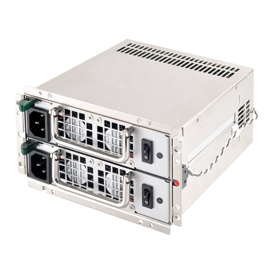
GM600-G
Endless power through redundancy
600+600W 24hour fully continuous power output
PS2 mini redundant power with 150mm(W) x 85mm(H) x 180mm(D)
80 PLUS Gold Certified
Active PFC (full range)
1+1 redundant configuration
Hot swappable design
Convenient pull-out handle bars
Industry-leading reliability
Support PMBus 1.2
Advertisement
Table of Contents

Subscribe to Our Youtube Channel
Related Manuals for SilverStone GEMINI GM600-G


Summary of Contents for SilverStone GEMINI GM600-G
- Page 1 GEMINI SERIES GM600-G Endless power through redundancy 600+600W 24hour fully continuous power output PS2 mini redundant power with 150mm(W) x 85mm(H) x 180mm(D) 80 PLUS Gold Certified Active PFC (full range) 1+1 redundant configuration Hot swappable design Convenient pull-out handle bars Industry-leading reliability Support PMBus 1.2...
- Page 2 The following manual and guides were carefully prepared by the SilverStone engineering team to help you maximize the potential of your SilverStone product. Please keep this manual for future reference when upgrading or performing maintenance on your system. A copy of this manual can also...
-
Page 3: Ac Input Specifications
SPECIFICATION SilverStone GEMINI GM600-G Mini Redundant Switching Power Supply 80 PLUS Gold PMBus 1.2 600W+600W 1. General This is the specification of Model GM600-G; it is intended to describe the functions and performance of the mini redundant power supply. The GM600-G 600 watts mini redundant power supply is featured with Active PFC (Power Factor Correction) capability and gold efficiency for 80+ and PMBus function meets IEC61000-3-2 and equips full range Input features. -
Page 4: Dc Output Specification
2.3 Input power factor correction (Active PFC) The power factor at 50% load shall be ≧ 0.9 at 230V input voltage. 2.4 Input current harmonics When the power supply is operated in 90-264 VAC of Sec. 2.1, the input harmonic current drawn on the power line shall not exceed the limits set by IEC61000-3-2 Class A and GB17625.1 standards. -
Page 5: Timing Requirements
Ripple and Noise shall be measured using the following methods: a) Measurements made differentially to eliminate common-mode noise. b) Ground lead length of oscilloscope probe shall be 0.25 inch. c) Measurements made where the cable connectors attach to the load. d) Outputs bypassed at the point of measurement with a parallel combination of 10uF tantalum capacitor in parallel with a 0.1uF ceramic capacitors. - Page 6 Item Description Units Tsb_on-delay Delay from AC being applied to +5VSB is being 1500 within regulation. Tac_on-delay Delay from AC being applied to all output voltages 2500 being Within regulation. Tvout_holdup All main output voltage stay within regulation after loss of AC Tpwok_holdup Delay from loss of AC deassertion of PWOK.
-
Page 7: Over Power Protection
3.5 Efficiency (80+ Gold) The efficiency should be measured module at 230 VAC and with external fan power source at specified loading. Input Voltage 20% Load 50% Load 100% Load 230 VAC Reference www.80plus.org all test conditions. 3.6 +5VSB (Standby) The +5VSB output is always on (+5V Standby) when AC power is applied and power switch is turned on. -
Page 8: Environmental Requirements
4.3 Over current protection The power supply should contain the OCP function on each hot swap module. The power supply should be shut down in a latch off mode while the respective output current exceeds the limit as shown in Table 8. When the latch has been cleared by toggling the PSON# single or cycling the AC input power. -
Page 9: Redundant Power Supply Function
7. Redundant power supply function 7.1 Redundancy The redundant power supply is N+1=N (600W+600W=600W) function power supply, each one module is redundancy when any one module was failed. To be redundant each item must be in the hot swap power supply module. - Page 10 8. PMBus 8.1 PMBus communication The PMBus serial bus communication devices for I2C data in the power supply shall be compatible with both SMBus 2.0 “high power” and I2C Vdd based power and drive. This bus shall operate at 3.3V but tolerant of 5V signaling.
- Page 11 8.2.2. PMBus command code summary PMBus Revison1.2 specification shall be used for the communication with system. Command code Command Name SMBus Transaction Type Number of Data Bytes CAPABILITY READ BYTE QUERY READ BYTE READ_ACV_IN READ WORD READ_ACI_IN READ WORD READ_VOUT READ WORD READ_IOUT READ WORD...
- Page 12 READ_TEMPERATURE_1 01H,81H READ_FAN_SPEED_1 12400 rpm 30H,70H READ_ FAN_SPEED_2 Reserved 00H,00H READ_POUT 250.00 W 61H,A8H READ_PIN 600.0 W 17H,70H PMBus_REVISION MFR_ID SilverStone 4BH,49H,4EH,54H,52H,4FH,4EH,20H, 20H,20H,20H,20H,20H,20H,20H,20H MFR_MODEL SST-GM600-G 4DH,56H,50H,2DH,36H, 30H,30H,56H, 50H,50H, 20H,20H,20H,20H MFR_ REVISION 41H,30H MFR_SERIAL_NO. 201312120001 32H,30H,31H,33H,31H,32H,31H,32H,30H, 30H,30H,31H,20H,20H,20H,20H MFR_VIN_MIN 100 VAC 00H,64H...
- Page 13 Command code= B0h Command Name (USER_DATA_00) Bit Number Status Bit Name Meaning Reserved Default=0 Reserved Default=0 Reserved Default=0 Reserved Default=0 Reserved Default=0 Reserved Default=0 PS_ON_Status PS_OFF =0,PS_ON =1 AC_Status (Must have12V) AC OK =0,AC Fail =1 8.2.3. PMBus Command Protocol Figure 8.2.3-1 PMBus command protocol for the two steps (Figure 8.2.3-1).
-
Page 14: Mean Time Between Failures (Mtbf)
9. Reliability 9.1 Mean time between failures (MTBF) The MTBF of the power supply shall be calculated utilizing the Part-Stress Analysis method of MIL-217F or Bell core RPP. The calculated MTBF of the power supply shall be greater than 100,000 hours under the following conditions: Full rated load 120V AC input... - Page 15 NO. G11223840...
Need help?
Do you have a question about the GEMINI GM600-G and is the answer not in the manual?
Questions and answers