Table of Contents
Advertisement
Quick Links
Advertisement
Table of Contents

Related Manuals for Texas Instruments TMP392EVM


Summary of Contents for Texas Instruments TMP392EVM
- Page 1 TMP392EVM User's Guide Literature Number: SNIU040 November 2019...
-
Page 2: Table Of Contents
..............Dual-Channel Resistor Programmable Trip Points .................... Manual Trip Test and Reset ....................... Open-Drain Output ........................Board Layout ....................Schematic and Bill of Materials Table of Contents SNIU040 – November 2019 Submit Documentation Feedback Copyright © 2019, Texas Instruments Incorporated... - Page 3 The sensor is also located on a perforated portion of the PCB that can be separated from the main board for prototyping. The TMP392EVM does not require any calibration or software programming, as the trip points are programmed through two resistors. This document provides detailed information about the device operation and evaluation board features.
-
Page 4: Trademarks
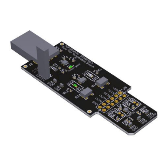
All trademarks are the property of their respective owners. Overview The TMP392EVM allows users to evaluate the performance of the TMP392 dual-trip programmable temperature switch. The EVM comes in a USB stick form factor that can plug into a USB port to supply power and begin the evaluation of the temperature switch. -
Page 5: Tmp392Evm Kit Contents
Overview www.ti.com TMP392EVM Kit Contents Table 1 summarizes the contents of the TMP392EVM kit. Figure 1 shows all of the included hardware. Table 1. TMP392EVM Kit Contents Item Quantity PCB Test Board: TMP392EVM USB Cable Extender EVM Hardware Overview and Operation... -
Page 6: Dual-Channel Resistor Programmable Trip Points
+30°C to +105°C range. These settings can be found in the TMP392 device data sheet. On the TMP392EVM, resistors R3 and R5 are populated to set the trip points for SETA and SETB, respectively. These are located on the same breakout board where the TMP392 is located, and are designated as RSETA and RSETB. -
Page 7: Board Layout
NOTE: This PCB will not withstand temperatures of 150°C for extended periods of time because it was not manufactured with high-temperature material. Schematic and Bill of Materials Figure 6. TMP392 Evaluation Board Schematic SNIU040 – November 2019 TMP392EVM User's Guide Submit Documentation Feedback Copyright © 2019, Texas Instruments Incorporated... - Page 8 Dual-Trip, Resistor- Programmable Texas Instruments TMP392A2DRLR Temperature Switch Dual Buffer/Driver SN74LVC2G240D With 3-State Texas Instruments Outputs Header, 100 mil, Samtec TSW-106-07-G-D 6x2, Gold, TH TMP392EVM User's Guide SNIU040 – November 2019 Submit Documentation Feedback Copyright © 2019, Texas Instruments Incorporated...
- Page 9 0.1 W, 0603 'RES, 90.9 k, 1%, CRCW060310K5F 90.9k Vishay-Dale 0.1 W, 0603 RES, 0, 5%, 0.063 CRCW04020000Z0 W, AEC-Q200 Vishay-Dale Grade 0, 0402 SNIU040 – November 2019 TMP392EVM User's Guide Submit Documentation Feedback Copyright © 2019, Texas Instruments Incorporated...
- Page 10 STANDARD TERMS FOR EVALUATION MODULES Delivery: TI delivers TI evaluation boards, kits, or modules, including any accompanying demonstration software, components, and/or documentation which may be provided together or separately (collectively, an “EVM” or “EVMs”) to the User (“User”) in accordance with the terms set forth herein.
- Page 11 www.ti.com Regulatory Notices: 3.1 United States 3.1.1 Notice applicable to EVMs not FCC-Approved: FCC NOTICE: This kit is designed to allow product developers to evaluate electronic components, circuitry, or software associated with the kit to determine whether to incorporate such items in a finished product and software developers to write software applications for use with the end product.
- Page 12 www.ti.com Concernant les EVMs avec antennes détachables Conformément à la réglementation d'Industrie Canada, le présent émetteur radio peut fonctionner avec une antenne d'un type et d'un gain maximal (ou inférieur) approuvé pour l'émetteur par Industrie Canada. Dans le but de réduire les risques de brouillage radioélectrique à...
- Page 13 www.ti.com EVM Use Restrictions and Warnings: 4.1 EVMS ARE NOT FOR USE IN FUNCTIONAL SAFETY AND/OR SAFETY CRITICAL EVALUATIONS, INCLUDING BUT NOT LIMITED TO EVALUATIONS OF LIFE SUPPORT APPLICATIONS. 4.2 User must read and apply the user guide and other available documentation provided by TI regarding the EVM prior to handling or using the EVM, including without limitation any warning or restriction notices.
- Page 14 Notwithstanding the foregoing, any judgment may be enforced in any United States or foreign court, and TI may seek injunctive relief in any United States or foreign court. Mailing Address: Texas Instruments, Post Office Box 655303, Dallas, Texas 75265 Copyright © 2019, Texas Instruments Incorporated...
- Page 15 TI products. TI’s provision of these resources does not expand or otherwise alter TI’s applicable warranties or warranty disclaimers for TI products. Mailing Address: Texas Instruments, Post Office Box 655303, Dallas, Texas 75265 Copyright © 2019, Texas Instruments Incorporated...
Need help?
Do you have a question about the TMP392EVM and is the answer not in the manual?
Questions and answers