Advertisement
Quick Links
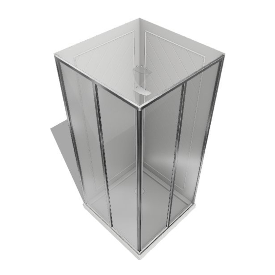
Cornerview Shower Enclosure, Base & Backwall
S
E
HOWER
NCLOSURE
IMPORTANT
DreamLine
reserves the right to alter, modify or redesign products at any time without prior notice.
®
For the latest up-to-date technical drawings, manuals, warranty information or additional details please refer
to your model's web page on DreamLine.com
STEP 1:
Shower Base Installation Instructions
STEP 2:
Shower Backwall Installation Instructions
STEP 3:
Shower Enclosure Installation Instructions
For more information about DreamLine
CORNERVIEW SHOWER ENCLOSURE, BASE & BACKWALL
, B
& B
ASE
ACKWALL
Shower Doors, Tub Doors & Enclosures, please visit DreamLine.com
®
I
I
NSTALLATION
©2017 DreamLine. All Rights Reserved
NSTRUCTIONS
Advertisement

Related Manuals for Dreamline DL-6150


Summary of Contents for Dreamline DL-6150
- Page 1 Shower Base Installation Instructions STEP 2: Shower Backwall Installation Instructions STEP 3: Shower Enclosure Installation Instructions For more information about DreamLine Shower Doors, Tub Doors & Enclosures, please visit DreamLine.com ® ©2017 DreamLine. All Rights Reserved CORNERVIEW SHOWER ENCLOSURE, BASE & BACKWALL...
- Page 2 For the latest up-to-date technical drawings, manuals, warranty information or additional details please refer to your model’s web page on DreamLine.com Color options: --- - White...
- Page 3 “Detailed Diagram of Shower Door Components”. If the unit has been damaged, has a finishing defect, or has missing parts, please contact our customer support department within 3 business days of the delivery date. Please note that DreamLine ®...
- Page 4 ©2018 DreamLine. All Rights Reserved SLIMLINE SHOWER BASE manual Ver 5 Rev 9 03/2018...
- Page 5 ©2018 DreamLine. All Rights Reserved SLIMLINE SHOWER BASE manual Ver 5 Rev 9 03/2018...
- Page 6 ©2018 DreamLine. All Rights Reserved SINGLE THRESHOLD SHOWER BASE Center Drain Configuration MODEL SPECIFICATION D (in) W (in) D1 (in) W1 (in) DLT-1132320 32"× 32" 32" 32" 15" 16" DLT-1136360 36"× 36" 36" 36" 15" 18" DLT-1132420 32” x 42”...
- Page 7 ©2018 DreamLine. All Rights Reserved SINGLE THRESHOLD SHOWER BASE Left-Hand Drain Configuration MODEL SPECIFICATION D (in) W (in) D1 (in) W1 (in) DLT-1130601 30"×60" 30" 60" 15" 12" DLT-1132601 32"×60" 32" 60" 15" 12" DLT-1134601 34"×60" 34" 60" 17" 12"...
- Page 8 ©2018 DreamLine. All Rights Reserved SINGLE THRESHOLD SHOWER BASE Right-Hand Drain Configuration MODEL SPECIFICATION D (in) W (in) D1 (in) W1 (in) DLT-1130602 30"×60" 30" 60" 15" 12" DLT-1132602 32"×60" 32" 60" 15" 12" DLT-1134602 34"×60" 34" 60" 17" 12"...
- Page 9 ©2018 DreamLine. All Rights Reserved NEO ANGLE SHOWER BASE MODEL SPECIFICATION W (in) A (in) B (in) C (in) DLT-2036360 36"×36" 36" 18 5/16" 25" 12" DLT-2038380 38"×38" 38" 20 5/16" 25" 12" DLT-2040400 40"×40" 40" 22 5/16" 25" 14 3/8"...
- Page 10 ©2018 DreamLine. All Rights Reserved QUARTER ROUND SHOWER BASE MODEL SPECIFICATION W (in) C (in) R (in) DLT-7033330 33"×33" 33" 12" 21 5/8" DLT-7036360 36"×36" 36" 12" 21 5/8" DLT-7038380 38"×38" 38" 12" 21 5/8" SLIMLINE SHOWER BASE manual Ver 5 Rev 9...
- Page 11 ©2018 DreamLine. All Rights Reserved DOUBLE THRESHOLD SHOWER BASE Corner Drain Configuration MODEL SPECIFICATION W (in) C (in) DLT-1032320 32"×32" 32" 12" DLT-1036360 36"×36" 36" 12" SLIMLINE SHOWER BASE manual Ver 5 Rev 9 03/2018...
- Page 12 ©2018 DreamLine. All Rights Reserved DOUBLE THRESHOLD SHOWER BASE Left-Hand Drain Configuration MODEL SPECIFICATION D (in) W (in) D1 (in) W1 (in) DLT-1034481 34"×48" 34" 48" 17" 12" DLT-1036481 36"×48" 36" 48" 18" 12" DLT-1036541 36"×54" 36" 54" 18" 12"...
- Page 13 ©2018 DreamLine. All Rights Reserved DOUBLE THRESHOLD SHOWER BASE Right-Hand Drain Configuration MODEL SPECIFICATION D (in) W (in) D1 (in) W1 (in) DLT-1034482 34"×48" 34" 48" 17" 12" DLT-1036482 36"×48" 36" 48" 18" 12" DLT-1036542 36"×54" 36" 54" 18" 12"...
- Page 14 ©2018 DreamLine. All Rights Reserved Shower Base Cross Section Diagram Cement board Finished Wall Shower Base (2"×4") Stud Mortar Drain* * not included SLIMLINE SHOWER BASE manual Ver 5 Rev 9 03/2018...
- Page 15 ©2018 DreamLine. All Rights Reserved Shower Base Installation - Preparation 1. Ensure that the floor and the studs are at right angles. Provide a 5”×5” opening in the sub- floor for the drain. The 2” PVC waste pipe should extend above the surface of the...
- Page 16 ©2018 DreamLine. All Rights Reserved 2. Install the shower drain (NOT INCLUDED) according to the drain installation manual (supplied with the drain). See Fig. 3 for example Fig. 3 3. Place the tray into the designated position so that the Drain cutout drops around the Drain Pipe and butt the Shower Base up against the studs.
- Page 17 ©2018 DreamLine. All Rights Reserved 4. Level the tray and place marks on the studs above the upper edge of the tile flange. See Fig. 5 for details. Level base in two directions Fig. 5 5. Mix the bedding material (Mortar, cement-sand mix, etc.) Concrete...
- Page 18 ©2018 DreamLine. All Rights Reserved 6. After the bedding material has been before poured and it sets, place the shower base into the position with the drain assembly sliding over the PVC waste pipe. It will be necessary to push...
- Page 19 ©2018 DreamLine. All Rights Reserved Fig. 9 SLIMLINE SHOWER BASE manual Ver 5 Rev 9 03/2018...
- Page 20 To maximize the life of your door, it is important to regularly inspect the glass and other hardware for misalignment, proper attachment, and/or damage. Contact DreamLine with any questions or concerns. SLIMLINE SHOWER BASE manual Ver 5 Rev 9 03/2018...
- Page 21 TEL: 866-731-2244 FAX: 866-857-3638 REAM INE.COM For more information on DreamLine ® Shower Doors Enclosures please visit DreamLine.com...
- Page 22 HOWER NSTALLATION NSTRUCTIONS IMPORTANT DreamLine reserves the right to alter, modify or redesign products at any time without prior notice. For the latest up-to-date technical drawings, manuals or any other details please refer to your model’s web page on BathAuthority.com Please read these instructions carefully before installing.
- Page 23 1. Please note that you should consult your local building codes with questions on installation compliance standards. Building and plumbing codes may vary by location, and DreamLine is not responsible for code compliance standards for your project. 2. This acrylic wall system is specially designed to be installed over any solid surface. If you are installing the acrylic walls over the existing tiles, remove all loose tiles before the installation.
- Page 24 Before discarding the carton, check for small hardware bags that may have fallen to the bottom of the box. If any parts are damaged or missing, please contact DreamLine for replacement. The shipping boxes may contain extra parts not used in your model configuration.
- Page 25 Preparation for Installation of Side Panel ATTENTION: Side Panel If you are installing a shower enclosure with a wall Wall Profile profile, you can hide the edge of the Side panel (01) behind the wall profile. Wall See Fig. 1 for details. Side Panel Wall Profile Wall...
- Page 26 2. Measure the walls of the shower from the 1” (one inch) line in the corner (from Step. 1) to the points where you want Side panels (01) to end. The distances are “D1” and “D2”. NOTE: “D2” Shows wall with the fixture. See Fig.
- Page 27 4. Place the Side panel (01) on a flat piece of plywood or particle board. Use a sharp industrial knife and a T- square to score along the marked wide ends of the Side panel and continue scoring until you have fully cut through the panel.
- Page 28 1" 5. Take exact measurements of the fixture on the wall: • from the 1” (one inch) line in the corner of the shower to the fixture: (A, B, C) • from the bottom of the wall of the shower to the fixture: (E, F).
- Page 29 7. Drill the holes for the fixtures in the Side panel (01) using the proper diameter saw bit or a handheld jig saw. See Fig. 9 for details. Acrylic Side Panel Installation Instruction 8. Attach the Corner cover (02) to the corner of the shower and mark the drilling holes through predrilled...
- Page 30 . 11 9. Mount the Corner cover (02) to the corner of the shower using the Countersunk screws ST4.2×40 (07). Do not fully tighten the screws at this time; leave them loose for further installation. See Fig. 12 and Fig. 13 for details .
- Page 31 . 13 10. Apply the sealant to the entire surface of the reverse side of the Side panel (01). Also, apply the sealant around the drilled holes. See Fig. 14 for details. . 14 Q-Wall 4 manual Ver 1 Rev 2 08/2015...
- Page 32 11. Slide the narrow edge of the Side panel (01) behind the Corner cover (02). Align trimmed edge of the Side panel (from Step. 4) with the marked line on the wall (in Step. 2) and push the Side panel against the wall.
- Page 33 14. Once Side panels (01) aligned, fasten tight the Corner cover (02) to secure the Side panels. Cover the screw holes with the Decorative cover (08). See Fig. 17 for details. . 17 ATTENTION; Side Panel Prior to the next step, please be sure the part of the wall for installation of the Decorative edge Wall molding (03) is clean, dry and free from soap, oil...
- Page 34 16. Apply caulk along the top edge of the Side panels (01) and along the connection of the bottom edges of the Side panels with the Shower base. See Fig. 19 for details. ATTENTION: Installation of “QWALL-4” Acrylic shower wall is complete. If you want to install Glass shelves (05) to your Shower, follow to the next step.
- Page 35 3 1/2" 18. Mark the location for the Shelf brackets (04) according to the measurements in Fig. 20 and Fig. 21.1. 3 1/2" Drill the holes using Ø5/16” drill bit and insert the Wall anchors (06). 3 1/2" See Fig. 21 for details. Ø...
- Page 36 . 23 Product maintenance To ensure long lasting life for your acrylic back walls, wipe them off after each use with a soft cloth. To clean the acrylic back walls use non-abrasive sprays or cream based cleaners. Never use abrasive cleansers, metal brushes or scrapers that could scratch or dull the surface. Acrylic cleaning procedure: Acrylic should be cleaned with warm water and a clean, non-abrasive cloth.
- Page 37 TEL: 866-731-2244 FAX: 866-857-3638 WWW. UTHORITY.COM For more information on DreamLine Shower Back Wall please visit www.BathAuthority.com Q-Wall 4 manual Ver 1 Rev 2 08/2015...
- Page 38 ® reserves the right to alter, modify or redesign products at any time without prior notice. Please refer to the model’s web page on DreamLine.com for the latest technical drawings, installation manuals, warranty information or additional product details. Cornerview Model#...
-
Page 39: Table Of Contents
Table of Contents Page # Section title Preparation Tools Detailed Diagram of Shower Door Components Parts List & Shower Enclosure Plan view Installation Steps 6-11 Product Maintenance ©2018 DreamLine. All Rights Reserved CORNERVIEW/FRENCH CORNER Shower Enclosure manual Ver 4 04/2018... -
Page 40: Preparation
2. Please note that you should consult your local building codes with questions on installation compliance standards. Building and plumbing codes may vary by location, and DreamLine ® not responsible for code compliance standards for your project and will not accept any returns. -
Page 41: Tools
Before discarding the carton, check for small hardware bags that may have fallen to the bottom of the box. If any parts are damaged or missing, please contact DreamLine for replacement. The shipping boxes may contain extra parts not used in ®... -
Page 42: Detailed Diagram Of Shower Door Components
Detailed Diagram of shower door components CORNERVIEW/FRENCH CORNER Shower Enclosure manual Ver 4 04/2018... -
Page 43: Parts List & Shower Enclosure Plan View
Parts List Part# DESCRIPTION Part# DESCRIPTION Wall profile Round head screw ST4.2x10 2pcs 4pcs Stationary glass assembly Decorative cover and washer 2pcs 4pcs Wall anchor 2pcs Door glass 8pcs Bolt M5x8 2pcs Rail connector 8pcs 8pcs Truss head screw ST4.2x40 Door wheel 8pcs Truss head screw ST4.2x10... -
Page 44: Installation Steps
Installation steps Place the Wall Profiles (#01) onto the threshold at a distance of 34-1/2” from the finished corner of the opening and mark their position on the wall at the outside threshold. Use a level to align the Wall outside Profiles (#01) vertically and mark the wall. - Page 45 Insert the Rail Connector (#04) into the guide rails of the Stationary Glass Assembly (#02). Drill a hole into the outer layer of the Rail Connector (#04), through the predrilled hole in the guide rails using an Ø1/8” drill bit. Fasten the top and bottom Rail Connector (#04) to the guide rails with the Flat Head Screw ST4.2×10 (#06).
- Page 46 Carefully align the assembled Stationary Glass Panels (#02) onto the Shower base and insert the Glass Profiles into the Wall Profiles (#01). (Fig 4) Fig 4 CORNERVIEW/FRENCH CORNER Shower Enclosure manual Ver 4 04/2018...
- Page 47 Insert two Door Wheels (#11) into the groove of the Upper Guide Rail, then attach the Door Glass (#03) to the Door Wheels (#11) using the Bolts M5×8 (#10). Repeat this procedure to attach the Door Glass (#03) to the Door Wheels (#11) in the Bottom Guide Rail.
- Page 48 For smoother operation, if necessary, adjust the position of the Door Wheels (#11) within the slot in the Door Glass (#03) rail. Perform any final adjustments of the assembled unit within the Wall Profiles (#01) and make certain that the bottom rails are tight to the threshold. From inside the shower, drill holes into the first layer of the Wall Profile and the Glass Profile (Fig 6.2) using an Ø1/8”...
- Page 49 Use a good quality mildew-resistant silicone to seal the connections between the Wall Profiles and the walls, and where the Bottom Guide Rail meets the threshold. (Fig 7) Allow 24 hours for the silicone to cure before using the shower. Hours Fig 7 CORNERVIEW/FRENCH CORNER Shower Enclosure manual Ver 4 04/2018...
-
Page 50: Product Maintenance
NOTE: To maximize the life of your door, it is important to regularly inspect the glass and all hardware for misalignment, proper attachment, and/or damage. Contact DreamLine with any questions or concerns. ® DreamLine shower doors and enclosures are designed not to leak when ®... - Page 51 TEL: 866-731-2244 FAX: 866-857-3638 DREAMLINE.COM For more information on DreamLine Shower Doors and Enclosures please visit DreamLine.com ® ©2018 DreamLine. All Rights Reserved...
Need help?
Do you have a question about the DL-6150 and is the answer not in the manual?
Questions and answers