Table of Contents
Advertisement
Quick Links
.
4K MEMORY CARD CAMERA RECORDER
GY-HM200U/GY-HM200E
GY-HM170U/GY-HM170E
INSTRUCTIONS
.
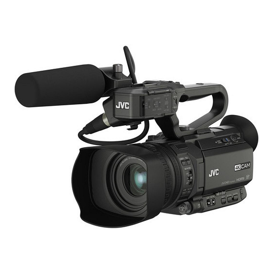
The illustration here shows how the handle unit is attached using the unit supplied with
GY-HM200U/GY-HM200E.
GY-HM170U/GY-HM170E do not come with a handle unit.
The specifications and appearance of this product are subject to changes for further improvement
without prior notice.
Please check the latest version of the INSTRUCTIONS from the following Mobile User Guide. You can
also download the PDF from the Mobile User Guide.
Mobile User Guide
When you are outside, you can refer to the instructions from your Android phone or iPhone.
http://manual3.jvckenwood.com/pro/mobile/global/
You can view the Mobile User Guide using the browser on your Android phone or iPhone.
For Customer Use:
Enter below the Serial No. which is located
on the body.
Retain this information for future reference.
Model No.
GY-HM200U/GY-HM170U
Serial No.
IM 1.02
Please read the following before getting started:
Thank you for purchasing this JVC product.
Before operating this unit, please read the
instructions carefully to ensure the best
possible performance.
In this manual, each model number is
described without the last letter (U/E) which
means the shipping destination.
(U: for USA and Canada, E: for Europe)
Only "U" models (GY-HM200U/GY-HM170U)
have been evaluated by UL.
Advertisement
Table of Contents

Related Manuals for JVC GY-HM200E


Summary of Contents for JVC GY-HM200E
- Page 1 You can view the Mobile User Guide using the browser on your Android phone or iPhone. Please read the following before getting started: Thank you for purchasing this JVC product. Before operating this unit, please read the instructions carefully to ensure the best possible performance.
- Page 3 FOR USA These are general IMPORTANT SAFEGUARDS and certain items may not apply to all appliances. IMPORTANT SAFEGUARDS Read these instructions. Keep these instructions. Heed all warnings. Follow all instructions. Do not use this apparatus near water. Clean only with dry cloth. Do not block any ventilation openings.
-
Page 4: Safety Precautions
RISK OF ELECTRIC undesired operation. SHOCK DO NOT OPEN Changes or modifications not CAUTION: approved by JVC could void the TO REDUCE THE RISK OF user’s authority to operate the ELECTRIC SHOCK. equipment. This equipment has been DO NOT REMOVE COVER (OR tested and found to comply with the BACK). - Page 5 POUR CANADA WARNING: TO PREVENT FIRE OR SHOCK HAZARD, DO NOT EXPOSE THIS UNIT TO RAIN OR ATTENTION MOISTURE. RISQUE D’ELECTROCUTION AVERTISSEMENT : POUR EVITER NE PAS OUVRIR LES RISQUES D’INCENDIE OU ATTENTION: D’ELECTROCUTION, NE PAS POUR EVITER TOUT RISQUE EXPOSER L’APPAREIL A LA D’ELECTROCUTION NE PAS PLUIE NI A L’HUMIDITE.
- Page 6 When the equipment is installed in a When using the AC adapter in cabinet or on a shelf, make sure that it areas other than the USA has sufficient space on all sides to allow The provided AC adapter features for ventilation (10 cm (3-15/16") or more automatic voltage selection in the AC on both sides, on top and at the rear).
- Page 7 FOR EUROPE IMPORTANT (for owners in the U.K.) This equipment is in conformity with the Connection to the mains supply in provisions and protection requirements of the United Kingdom. the corresponding European Directives. DO NOT cut off the mains plug from This equipment is designed for professional this equipment.
- Page 8 European representative of until it is no longer wobbly, and then plug JVC KENWOOD Corporation is: the larger end of the power cord in to an JVC Technical Services Europe GmbH AC outlet. Konrad-Adenauer-Allee 1-11 61118 Bad Vilbel FOR EUROPE...
- Page 9 Para Retirar a Bateria Recarregável ... do not modify or Pressione botão e puxe a bateria para fora. disassemble..do not expose the GY-HM200U/GY-HM200E battery to temperatures Empurre exceeding 60°C (140°F), as this may cause the battery to overheat, explode or catch fire.
-
Page 10: Table Of Contents
Contents Basic Shooting Procedures ......46 Selecting System Definition, File Format and Video Format ............. 47 Introduction Zoom Operation ..........49 Safety Precautions ..........4 Focus Operation ..........50 Contents ............10 Adjusting the Focusing by Face Detection ..53 Main Features .......... - Page 11 Text Input with Software Keyboard ....94 Configuring the Server for Downloading ..146 Menu Screen Hierarchical Chart ..... 95 Importing Metadata ........147 Camera Function Menu ........96 Uploading a Recorded Video Clip K ..148 User Switch Set Item ........98 Configuring the FTP Server for Uploading .
-
Page 12: Main Features
Web files can also be recorded High-performance CMOS sensor with a simultaneously. sensitivity of F5.6 For GY-HM200U/GY-HM200E, it is also possible to perform streaming while the recording is This camera recorder is built in with a high- ongoing. - Page 13 Professional-style switch layout and Content of this manual diverse video parameters All rights reserved by JVC KENWOOD Corporation. Unauthorized duplication or reprinting of this manual, Switches for Gain and White Balance are available in whole or in part, is strictly prohibited.
-
Page 14: Precautions For Proper Use
Precautions for Proper Transportation o Do not drop or hit this unit against a hard object when transporting. Power Saving Storage and Usage Locations o When this unit is not in use, be sure to set the o Allowable ambient temperature and humidity [POWER ON/OFF] switch to “OFF”... - Page 15 o We are not liable for any accidental loss of data Regular Inspection (Maintenance) stored on the SD card. Please back up any o Under normal environment, dust will important data. accumulate on the camera recorder when it is o Make use of the SD card within the prescribed used over a long period.
- Page 16 LCD Monitor and Viewfinder Copyright o The LCD monitor and viewfinder screen are o Any recordings made on this camera recorder manufactured using high-precision technology. that are played back for profit or public preview Black spots may appear on the LCD monitor and may infringe on the rights of the owner of the viewfinder screen, or red, blue, and/or white recordings.
- Page 17 Others o Do not insert objects other than the memory card into the card slot. o Do not block the vent on the unit. Blocking of the vent causes internal heating and may lead to burns and fires. Do not turn off the [POWER ON/OFF] switch or remove the power cable during recording or playback.
-
Page 18: Operation Modes
[Change to Remote Edit Mode?] screen on the camera or the web browser Remote Edit Mode * Selecting a mode other than the Metadata Edit mode via the web GY-HM200U/ browser, or selecting [Exit] on the [Remote Edit Mode] screen GY-HM200E only MODE Set Button Operation Modes... - Page 19 Operation Mode Description Camera Mode This is the camera shooting mode. The camera recorder starts up in Camera mode when the power is turned on. Camera images are output on the viewfinder and LCD monitor. When a recordable SD card is inserted, the camera recorder enters the recording standby mode. “STBY”...
-
Page 20: Names Of Parts
Names of Parts o Bottom A Built-in Microphone (A P65 [Audio Recording] ) G Visibility Adjustment Lever B Handle Unit K (A P38 [Adjusting the Viewfinder] ) (A P24 [Handle Unit K] ) H Battery * GY-HM170U/GY-HM170E does not come with (A P29 [Using a Battery Pack] ) the handle unit. -
Page 21: Side Control Panel
Side Control Panel E [TC/2] Time Code/User 2 Button Displays the time code setting screen. (A P69 [Setting Time Code Generator] ) You can also use it as a user button by assigning a specific feature in the menu setting to this button. (A P39 [Assignment of Functions to User Buttons] ) F LCD monitor... -
Page 22: Side Terminal Section
(A P140 [Connecting Wired Remote Control] ) Rear Terminal F [AUX] AUX Input Terminal (Φ3.5 mm) For connecting to receiver such as wireless GY-HM200U/GY-HM200E microphone. (A P65 [Audio Recording] ) G [x] Headphone Jack (Φ3.5 mm) (A P67 [Monitoring Audio Sound During... -
Page 23: Lcd Monitor
LCD Monitor F [C.REVIEW/4] Clip Review/User 4 Button For checking the most recently captured images. (A P73 [Viewing Recorded Videos Immediately (Clip Review)] ) You can also use it as a user button by assigning a specific feature in the menu setting to this button. -
Page 24: Handle Unit K
Handle Unit K J [INPUT1/INPUT2] Audio Input Terminal 1, 2 (XLR 3-pin x 2) (A P27 [Attaching the External Microphone O] ) K Cable Clamp for Microphone (A P27 [Attaching the External Microphone O] ) L Handle Terminal M [CH-1] CH1 Audio Input Signal Selection Switch Select the audio input terminal to record to CH1. -
Page 25: Lens Section
Lens Section A Filter Built-In Screw Transparent or UV filter for lens protection, or filters for various effects can be installed. Installable filter types: Φ62 mm P0.75 Memo : Remove the lens hood when installing the filter. (A P28 [Attaching/Detaching the Hood] ) B Focus Ring (A P50 [Focus Operation] ) C Zoom Ring... -
Page 26: Basic System Diagram
Basic System Diagram When handle unit is attached GY-HM200U/GY-HM200E/ Wireless Microphone Receiver Microphone GY-HM170U/GY-HM170E GY-HM200U/GY-HM200E only Headphone [INPUT1/INPUT2] [AUX] Handle Unit Battery Battery Chager IDX Battery Charger AA-VF8 SSL-JVC50 GY-HM200U/GY-HM200E BN-VF823 only [SDI OUT] [DC] SDI Cable [HDMI] AC Adapter... -
Page 27: Settings And Adjustments Before Use
Settings and Adjustments Adjusting the Grip Belt Before Use Open the pad and adjust the position of the grip belt accordingly. Attaching the Handle Unit K The handle unit is detached from the camera recorder unit in the factory shipment. * GY-HM170U/GY-HM170E does not come with the handle unit. -
Page 28: Attaching/Detaching The Lens Cap
Attaching/Detaching the Lens Cap Attaching/Detaching the Hood Before shooting, detach the lens cap. Attaching the Hood When this camera recorder is not in use, attach the lens cap to protect the lens. Align the markings on the camera recorder and Pinch the tabs on both sides of the lens cap to hood;... -
Page 29: Attaching The Tripod
Attaching the Tripod Use the screw hole at the bottom of this camera recorder. (3/8×16UNC, 1/4×20UNC) Use the screw hole that suits the tripod. To prevent the camera recorder from falling off, which may result in injuries or damages, read the “INSTRUCTIONS”... - Page 30 Removing the Battery Memo : If you charge the battery immediately after using GY-HM200U/GY-HM200E while the battery is still warm, it may not be fully charged. It is recommended that you charge the battery in an environment between 10 °C and 30 °C (50 °F and 86 °F).
-
Page 31: Using Ac Power (Dc In Power)
Power Status Display Using AC Power (DC IN Power) Use the supplied AC adapter to operate the camera recorder with AC power. Viewfinder Screen and LCD Monitor The power status is displayed on the display and menu screens. Display Description B 7.4V Currently powered by a battery. -
Page 32: Turning On/Off The Power
Menu Screen If the battery is not fully charged, the battery will be charged at the same time. (A P93 [Display and Description of the Menu Even when a fully charged battery is used, charge Screen] ) the battery briefly to confirm the remaining battery power. -
Page 33: Initial Settings
Initial Settings Memo : The menus and messages on the screen of the When the power is first turned on, the Initial Setting LCD monitor or viewfinder are displayed in the screen for performing the initial settings in the selected language. camera recorder appears. - Page 34 Changing the Time after Initial Setting 4 Press the Set button (R) after confirming the exit screen. Setting the Date/Time The [Initial Setting] screen appears. (A P114 [ Date/Time ] ) For U models 1 Select [System] B [Date/Time]. The [Date/Time] screen appears. 2 Set the date and time.
-
Page 35: Displays On The Lcd Monitor And Viewfinder
Displays on the LCD Display Screen (VF/LCD) in Media Mode (A P132 [Display Screen in Media Mode] ) Monitor and Viewfinder This is the screen display during clip playback in Media Mode. The display switches between three screen You can display the camera status, media types with every press of the [DISPLAY] button. -
Page 36: Status Screen
Status Screen USB Mode Screen This screen allows you to check the current This screen displays the USB mode. settings. To display the status screen, press the [STATUS] button in the normal screen. The status display differs according to the operation mode (two types). -
Page 37: Adjusting The Lcd Monitor And Viewfinder
Adjusting the LCD Monitor Adjusting the LCD Monitor and Viewfinder Tilt 90 degrees downward You can monitor video images on this camera Tilt 180 degrees recorder using the viewfinder, LCD monitor, or upward both. Normal LCD Inverted 1 Open the LCD cover. 2 Incline the LCD monitor to a position that enables easy viewing. -
Page 38: Adjusting The Viewfinder
Adjusting the Viewfinder 4 Adjust the brightness, contour, and contrast of the viewfinder screen. You can change the brightness and peaking of the Use the [VF Bright] menu to adjust the viewfinder screen according to your usage conditions. brightness of the viewfinder screen. Changing the brightness of the screen will not [Main Menu] B [LCD/VF] B [VF Bright] affect the recorded images. -
Page 39: Assignment Of Functions To User Buttons
Assignment of Functions Memo : Operations of the user buttons are interlocked to User Buttons with the menu settings. When the menu screen is displayed, these buttons function as the menu operation buttons. You can assign functions to the following buttons (A P92 [Basic Operations in Menu Screen] ) and use them as user buttons. -
Page 40: Sd Card
SD Card o When [Main Menu] B [System] B [Record Set] B [Record Format] B [Format] is set to “QuickTime” This camera recorder saves the recorded images System and audio sound on the SD card (sold separately) Resolution 2160p 1080i/1080p 480i/ 960p 480p in the card slot. - Page 41 Inserting an SD Card Removing the SD Card This camera recorder comes with two card slots 1 Check that the SD card to be removed is not (Slot A and B) for video/audio recording and being accessed (status indicator of the playback.
-
Page 42: Formatting (Initializing) Sd Cards
Switching the SD cards 1 Select [System] B [Media] B [Format When both card slots are inserted with SD cards, Media]. you can use the [SLOT SEL] button to switch the (A P113 [ Format Media ] ) card to use. 2 Select the slot of the SD card to be When the memory on an SD card is full during formatted and press the Set button (R). -
Page 43: Restoring The Sd Card
6 Formatting is complete. 3 Restoring starts. When formatting is complete, “Complete” appears and the camera recorder returns to the [Format Media] screen. Memo : Restoring... During formatting, menu operation is unavailable but you can start recording. However, this is only available when a recordable SD card is inserted in the other slot. -
Page 44: Clips Recorded To Sd Cards
Example: QuickTime Clips Recorded to SD Cards Folders in the SD Card AB CG00 01 The captured image is recorded into different Clip Number folders according to the [System] and [WFormat]/ A number in automatic [YFormat] settings. ascending order is assigned in the recording order. -
Page 45: Operation Lock Feature
Operation Lock Feature Operation lock does not apply to the following buttons and switches. [POWER ON/OFF] switch You can use this feature to prevent erroneous [AUDIO INPUT INPUT1]/[AUDIO INPUT camera operation. INPUT2] Audio input signal selection switch [CH-1]/[CH-2] Audio input signal selection switch O [AUDIO SELECT CH-1 AUTO/MANU]/[AUDIO SELECT CH-2 AUTO/MANU] Audio recording... -
Page 46: Shooting
Basic Shooting Shooting Procedures The [FULL AUTO] button of this camera recorder is set to “ON” by default, the following video items are automatically adjusted. Preparations Iris Gain Shutter White balance The audio recording level is also set to Auto, and audio from the built-in microphone is recorded. -
Page 47: Selecting System Definition, File Format And Video Format
Selecting System 1 Press the [REC] button to start recording to Definition, File Format and the SD card. This camera recorder has two [REC] buttons. Video Format Any of the [REC] buttons can be used to start/ stop recording by default. The tally lamp lights up in red during recording. - Page 48 o When [System] is set to “HD” or “HD+Web”, the Selecting a File Format options for slot A are: Select a file format in [WFormat]/[YFormat]. Record Format There are two file formats for selection. W Format W Resolution W Frame W Bit Rate AVCHD: Rate...
-
Page 49: Zoom Operation
Zoom Operation o When [System] is set to “HD+Web”, the options for slot B are: Record Format Adjusts the angle of view. Y Format Y Resolution Y Frame Y Bit Rate Optical zoom ratio: 1x to 12x Rate Dynamic zoom ratio: 12x to 24x QuickTime 960 x 540 3M (HQ) -
Page 50: Focus Operation
Focus Operation Set the zoom speed for “L”, “M” and “H” of the [ZOOM L/M/H] zoom speed switch individually. Increasing the value increases the zoom speed. (A P97 [Handle Zoom Speed L/Handle Zoom Speed M/Handle Zoom Speed H O] ) Memo : The zoom lever at the handle is disabled when “Off”... - Page 51 Setting to Auto Focus Temporarily Memo : (Push Auto Focus) Using the Focus Assist or Expanded Focus If [Push AF/AF Lock] is assigned to the user function makes it easier to focus. button, the camera recorder will shift to Auto (A P52 [Focus Assist Function] ) Focus mode temporarily and automatically (A P52 [Expanded Focus Function] )
- Page 52 Focus Assist Function 1 Press the [EXPANDED FOCUS/8] button. When the [F.ASSIST/1] button is pressed during “EXPANDED” (yellow color) appears on the shooting, the focused area is displayed in color. screen, and the center part of the image is This enables easy and accurate focusing. enlarged if this button is pressed for the first Select the color (blue, red or green) in the menu.
-
Page 53: Adjusting The Focusing By Face Detection
Adjusting the Focusing by 1 Assign the “Face Detect” function to any of Face Detection the user buttons. (A P39 [Assignment of Functions to User Buttons] ) This function detects human faces and 2 Focus the camera recorder on a person and automatically adjusts focus during Auto Focus. -
Page 54: Adjusting The Brightness
Adjusting the Brightness Selecting Specific Person from Several Persons 1 Hold down the user button that is assigned Adjust the brightness using Iris, Gain, Shutter with “Face Detect”. speed and ND filter according to the brightness of the object. The camera recorder will enter face selection mode and the face detection icon (q) will Adjusting the Brightness Automatically: blink. -
Page 55: Adjusting The Iris
Adjusting the Iris Memo : Pressing and holding the [FULL AUTO] button to enter the Full Auto mode also activates the Adjust the aperture of the lens iris according to the automatic brightness adjustment (AE) mode. In brightness of the subject. this case, the White Balance also enters into Auto mode forcibly. - Page 56 One Push Auto Iris Manual Iris (Manual Adjustment) Mode When [One Push Iris] is assigned to the user The aperture value (F-number) of the lens can be button, press this button in the Manual Iris mode to set manually. adjust the iris according to the brightness of the 1 Press and hold the [FULL AUTO] button to subject.
-
Page 57: Setting The Gain
Setting the Gain Manual Gain Mode (Manual Gain Switching) This function electrically boosts the light sensitivity 1 Press and hold the [FULL AUTO] button to when there is insufficient illumination on the object. set Full Auto mode to off. You can set the gain of the video amplifier Select the gain level of the video amplifier according to the brightness of the object. -
Page 58: Setting The Electronic Shutter
Setting the Electronic Manual Shutter Mode (Manual Shutter Switching) Shutter 1 Press and hold the [FULL AUTO] button to set Full Auto mode to off. You can change the shutter speed (time for each 2 Press and hold the [SHUTTER] button to shooting frame) using the electronic shutter enter Manual Shutter mode. -
Page 59: Setting The Nd Filter
Setting the ND Filter Frame Rate Shutter Mode Use the ND filter to keep the lens aperture in the appropriate range. 1/10000 1/4000 1/10000 1/10000 1/2000 1/4000 1/4000 1/1000 1/2000 1/2000 1/500 1/1000 1/1000 1/250 Step 1/500 1/500 1/120 1/250 1/250 1/100 1/120... -
Page 60: Adjusting The White Balance
Adjusting the White ND Filter Warning Display Balance In order to adjust the amount of light when you are shooting at a relatively bright location, the diameter of the iris may become extremely small, causing blurry effects to occur as a result. Adjust the white balance according to the color This phenomenon is known as “small aperture temperature of the lighting. - Page 61 Memo : 3 Press the Set button (R). Pressing and holding the [FULL AUTO] button Returns to the [White Balance] screen. to enter the Full Auto mode also activates the Automatic White Balance mode. In this case, the Iris, Gain and Shutter also enter into Auto mode White Balance forcibly.
- Page 62 Setting the [Preset Temp.] or [Alternative Memory A Mode (A), Memory B Mode Temp.] Values You can change both the color temperature Set to the white balance saved in Memory A or settings in the Preset mode in the menu. Memory B.
- Page 63 1 Select [Main Menu] B [Camera Process] B [White Balance] B [AWB Paint] and press 282min 00: 00: 00.00 100min the Set button (R). 50min Jan 24 , 2015 The White Paint Adjustment screen appears. 12 :34 :56 White Detection 3840x2160 30 p 150M Frame...
-
Page 64: Adjusting The Camera Image
Adjusting the Camera Using the Image Stabilizer Image Reduces blurring of images due to camera shake. 1 Check whether the image stabilizer feature The picture quality of the camera can be set using is turned ON or OFF. the [Camera Process] menu. If the image stabilizer icon (i/j) does not As the adjustments are shown on the screen, you appear on the screen display, the image... -
Page 65: Audio Recording
Audio Recording Memo : When the [AUX] terminal is not connected, [Main Menu] B [A/V Set] B [Audio Set] B [CH1 You can record audio from the two channels (CH1/ INT]/[CH2 INT] is fixed at “Int. Mic L”/“Int. Mic CH2) in synchronization with video images on this R”... - Page 66 o When the input channel is set to “INT” for Adjusting the Audio Recording Level both [CH1] and [CH2] You can select to adjust the audio recording levels 1 Set the [AUDIO SELECT CH-1 AUTO/ for the two channels (CH1/CH2) manually or MANU] switch to “MANU”.
-
Page 67: Monitoring Audio Sound During Recording Using A Headphone
Monitoring Audio Sound Memo : When [Main Menu] B [A/V Set] B [Audio Set] B During Recording Using a [Limiter] is set to “Off” while in the automatic Headphone adjustment mode, the limiter operates at -6 dBFS. When [A/V Set] B [Audio Set] B [Audio On FULL You can check the recorded audio using AUTO] is set to “SW Set”, you can switch the headphone. -
Page 68: Time Code And User's Bit
Time Code and User’s Bit Time Code Operation Mode Set the time code operation in [Main Menu] B [TC/ UB] B [TC Generator]. Time code and user’s bit data are recorded with the (A P103 [ TC Generator ] ) video in this camera recorder. -
Page 69: Setting Time Code Generator
Setting Time Code 2 Select the framing mode for the time code Generator generator (only when the frame rate setting is “60” or “30”). Set using [Main Menu] B [TC/UB] B [Drop Presetting the Time Code Frame]. (A P104 [ Drop Frame ] ) Time code and user’s bit data generated from the [Drop]: internal time code generator are recorded. - Page 70 Setting Time Code without Opening the 1 Select [Main Menu] B [TC/UB] B [TC Menu Preset] and press the Set button (R). (A P103 [ TC Preset ] ) The [TC Preset] screen appears. TC/UB 00:00:00:00 TC Preset Memo : Memo : Settings cannot be made in the following cases.
-
Page 71: Setting The User's Bit
Setting the User’s Bit 4 Check the values and press the Set button (R). The time code is set and the screen returns You can add the date, time or an 8-digit to the normal screen. hexadecimal number as the user’s bit to the To cancel the setting, press the [CANCEL/ recorded image. -
Page 72: Setting Zebra Pattern
Setting Zebra Pattern 1 Set [Main Menu] B [TC/UB] B [UB Mode] to “Preset”, and press the Set button (R). (A P103 [ UB Mode ] ) When the luminance level range for displaying zebra patterns is specified, diagonal lines (zebra pattern) are displayed at areas with the specified TC/UB luminance levels during shooting. -
Page 73: Viewing Recorded Videos Immediately (Clip Review)
Viewing Recorded Videos Caution : During Clip Review, only the [CANCEL/STOP] Immediately (Clip Review) and [REC] buttons are enabled. Press the [CANCEL/STOP] button to cancel clip You can check (review) the last recorded video clip review and return to “STBY” (recording standby) on the screen. -
Page 74: Recording Simultaneously At Two Different Definitions
Recording Dual Rec Simultaneously at Two If both the slots are loaded with recordable cards Different Definitions in the Dual Rec mode ([Slot Mode] is set to “Dual”), pressing the [REC] button starts recording simultaneously to the media in both By setting [System] to “HD+Web”, you can record the slots. - Page 75 Caution : 2 Start recording. To perform recording in the Dual Rec mode, it is Insert recordable media in both slots, and recommended that you start recording by press the [REC] button. making use of two cards with the same capacity In the Dual Rec mode, recording to the media and from the formatted state.
-
Page 76: Backup Rec
Backup Rec 1 Set [Main Menu] B [System] B [Record Set] B [Slot Mode] to “Backup”. (A P117 [ Slot Mode ] ) The Backup Rec mode allows you to make use “BACKUP” appears on the display screen. of the media in slot B for backup recording by controlling the starting and stopping of recording in slot B without using the [REC] button. - Page 77 3 Start normal recording (normal recording 5 Stop backup recording. into slot A) Select [STBY] in [Main Menu] B [System] B Press any of the [REC] buttons. [Record Set] B [Slot Mode] B [Backup Rec] Recording into the media in slot A starts. and press the Set button (R).
-
Page 78: Special Recording
Special Recording 1 Set [Rec Mode] to “Pre Rec”. (A P116 [ Rec Mode ] ) Set [Main Menu] B [System] B [Record Besides the normal recording mode, four special Set] B [Rec Mode] to “Pre Rec”. recording methods are available in this camera recorder. -
Page 79: Clip Continuous Rec
Clip Continuous Rec 3 Pause recording. Press the [REC] button again to pause In normal recording, when the recording stops, the image, audio, and accompanying data from recording. The display changes (“RRECC” the start till the end of the recording are recorded B “STBYC”... -
Page 80: Frame Rec
Frame Rec Memo : Clip Continuous Rec cannot be used in the In normal recording, when the recording stops, the following cases. image and accompanying data from the start till the When [Main Menu] B [System] B [Record end of the recording are recorded as one “clip” on Set] B [System] is set to “HD”... -
Page 81: Interval Rec
Interval Rec 2 Set the number of frames to record in [Rec In normal recording, when the recording stops, the Frames]. image and accompanying data from the start till the Set using [Main Menu] B [System] B [Record end of the recording are recorded as one “clip” on Set] B [Rec Mode] B [Rec Frames]. -
Page 82: Splitting The Clips Freely (Clip Cutter Trig)
Splitting the Clips Freely 3 Set the time interval to start recording in (Clip Cutter Trig) [Interval Rec]. Set using [Main Menu] B [System] B [Record Set] B [Rec Mode] B [Rec Interval]. You can split the clips freely without having to stop (A P116 [ Rec Interval ] ) recording during shooting. -
Page 83: Playing Recorded Clips
Playing Recorded Clips F [C.REVIEW/4] Button Switches the selection status of the clip selected by the cursor. To play back clips recorded on SD cards, switch to Clips being selected are displayed with the Media mode. check mark. Press and hold the [MODE] selection button in G [ZEBRA/5] Button Camera mode to enter Media mode. - Page 84 Memo : Memo : Dependent on the settings for [Main Menu] B Clips appended with OK marks cannot be [System] B [Record Set] B [Record Format] B deleted on the camera recorder. [System]/[WResolution]/[YResolution]/ When [Main Menu] B [System] B [Record Set] [WFrame Rate]/[YFrame Rate]/[WBit Rate], B [Record Format] B [WFormat] is set to and [YBit Rate].
-
Page 85: Actions
Actions K Network Connection Icon K The network connection status is displayed The action selection screen is displayed when the when [Main Menu] B [System] B [Network] User 5 ([ZEBRA/5]) button is pressed. is set to “On”. The following operations can be performed. This icon is not displayed when “Off”... -
Page 86: Playing Back
Playing back Item Description FTP Upload Uploads a clip to the FTP server. Use the operation buttons on the side control panel This Clip: of the camera recorder to play back. Uploads the clip pointed by the cursor. Selected Clips: Uploads the clips selected (appended with check mark). -
Page 87: Deleting Clips
Deleting Clips Time Code Playback Time code or user’s bit recorded on an SD card can be displayed on the LCD monitor and viewfinder. Delete clip. Memo : The time code is also superimposed on the video signal output from the [SDI OUT] terminal. If a section without time code is played back, the time code will stop. -
Page 88: Appending/Deleting Ok Mark
Appending/Deleting OK 3 Select [Delete Clips] B [This Clip] and press Mark the Set button (R). A screen to confirm deletion appears. You can append OK marks to the clips for important scenes. Clips appended with OK marks cannot be deleted, thus protecting the important clips. -
Page 89: Selecting And Performing Operations On Multiple Clips
During Playback or Pause Screen Selecting Multiple Clips Randomly 1 Press [LOLUX/3] button during clip 1 Move the cursor to a clip without a check playback. mark, and press the [C.REVIEW/4] button. If the clip does not have an OK mark, an OK A green check mark appears on the clip. -
Page 90: Selecting Multiple Clips Consecutively
Selecting Multiple Clips Consecutively 5 Press the Set button (R) to confirm the range. 1 Press the [ZEBRA/5] button. The check marks change from magenta to 2 Select “Select Range” in the action green. selection screen, and press the Set button Pressing the [ZEBRA/5] button while the (R). -
Page 91: Trimming Recorded Clips
Trimming Recorded Clips C Trimming information W or Y : Indicates the available space in the storage media (W or Y) You can extract (trim) the necessary parts of a clip : Indicates the time code of the in recorded in the SD card. point The trimmed clip is saved as a new file on the same : Indicates the time code of the out... -
Page 92: Basic Operations In Menu Screen
Basic Operations in Menu A [MENU/THUMB] Button Displays the menu screen. The [Main Screen Menu] screen is displayed by default. During normal usage, [Main Menu] is Press the [MENU/THUMB] button on the LCD displayed if the previous menu operation ended at [Main Menu], and [Favorites monitor to display the menu screen on the LCD monitor and viewfinder. -
Page 93: Display And Description Of The Menu Screen
Changing Setting Values Display and Description of the Menu Screen Selecting Menu Items Display Settings Audio Meter Battery Date/Time Display Settings Date Style Audio Meter Time Style 24hour Battery Time Shutter Date/Time Cancel Date Style A Menu Item to Change Time Style 24hour Menu item to be changed. -
Page 94: Text Input With Software Keyboard
Text Input with Software Keyboard A Character Entry Field Field for entering the title. Use the software keyboard to enter the [Setup You can enter up to 8 characters for the File] subname, [Clip Name Prefix], and the settings [Setup File] subname or up to 4 characters under [Network] B [Settings]. -
Page 95: Menu Screen Hierarchical Chart
Menu Screen Hierarchical - [Color Matrix] ....... (A P 102) Chart - [Color Gain] ......... (A P 102) - [Reset Process] ......(A P 102) - [TC/UB...] ........(A P 103) [Main Menu...] ........(A P 95) - [TC Generator] ......(A P 103) - [Camera Function...] ...... -
Page 96: Camera Function Menu
Camera Function Menu AE Speed For setting the convergence speed during AE (Auto Exposure). Menu screen for specifying operation settings [Setting Values: RFast, Middle, Slow] during shooting. This item can only be selected in the Camera AGC Limit mode. For setting the maximum gain value of “AGC”, Bars which electrically boosts the sensitivity level according to the brightness automatically. - Page 97 Iris Dial For setting the position in the white balance switch For assigning the iris, shutter or AE level [WHT.BAL B/A/PRST] to assign the FAW (Full adjustment to the iris dial. [Setting Values: AE Level, Shutter, RIris] Auto White Balance) function. [Setting Values: B, A, PRST, RNone] AF Speed GAIN L/GAIN M/GAIN H...
-
Page 98: User Switch Set Item
User Switch Set Item Face Detect For specifying the operation when any of the USER1 to USER9, LCD KEY▲/LCD [USER1]-[USER9], [LCD KEY▲], [LCD KEY▶], KEY▶/LCD KEY▼/LCD KEY◀ [LCD KEY▼], or [LCD KEY◀] items is set to “Face Detect”. By assigning one of the following functions to each Select the control to track results of face detection. - Page 99 AE/FAW Lock Expanded Focus For specifying the operation when any of the For specifying the operation when any of the [USER1]-[USER9], [LCD KEY▲], [LCD KEY▶], [USER1]-[USER9], [LCD KEY▲], [LCD KEY▶], [LCD KEY▼], or [LCD KEY◀] items is set to [LCD KEY▼], or [LCD KEY◀] items is set to “AE/FAW Lock”.
-
Page 100: Camera Process Menu
Camera Process Menu 9 Stretch Level Stretch amount increases when a larger value is specified. Menu screen for adjusting the quality of camera [Setting Values: 1 to 5 (R 3)] images. Memo : This item cannot be selected in the Media mode. This item is displayed only when [Black Toe] is Detail set to “Stretch”. - Page 101 9 Sensitivity 9 Gamma Level For setting the response speed of the “Knee” This item can be specified separately when [Gamma] is set to “Standard” or “Cinema”. operation when [Knee] is set to “Auto”. Increase the number: Set to “Slow” when shooting an object under a Enhances the gradation of black.
-
Page 102: Detail/Adjust Item
Detail/Adjust Item Color Matrix For setting the color matrix. V/H Balance Cinema Subdued: For setting the H/V balance to enhance contour Sets to a subdued color matrix that is similar to (detail) in the horizontal (H) or vertical (V) direction. the screen characteristics of movies. -
Page 103: Tc/Ub Menu
TC/UB Menu AWB Paint For adjusting the R (red)/B (blue) component in the AWB (Auto White Balance) mode. Menu screen for setting time code and user’s bit. For details, refer to “[Adjusting the White Balance] This item cannot be selected in the Media mode, (A P 60)”. -
Page 104: Lcd/Vf Menu
LCD/VF Menu 9 Preset For setting the user’s bit. (Digit by digit) Display : AB CD EF 01 Item for specifying settings related to the LCD (A P71 [Presetting the User’s Bit] ) monitor or viewfinder screen. Memo : This menu screen can be used to specify settings related to the Focus Assist mode, zebra pattern When [UB Mode] is set to “Date”... -
Page 105: Shooting Assist Item
Shooting Assist Item VF Bright For setting the brightness of the viewfinder screen. Focus Assist Increasing the value increases the brightness. For setting whether to add color to the contour of [Setting Values: -10 to +10 (R 0)] the focused image upon switching the image to VF Contrast black-and-white. -
Page 106: Marker Settings Item
Marker Settings Item 9 Aspect Marker For specifying how boundary markers are to be For setting the marker and safety zone, which are used to indicate the parts of an image that are useful in helping you determine the angle of view beyond the range of the aspect ratio selected in for the image according to the shooting purpose. -
Page 107: Display Settings Item
Display Settings Item Record Format This menu is used to set the displays on the LCD For setting whether to display the video format monitor and viewfinder screen. during recording or playback. [Setting Values: ROn, Off] Zoom Media Remain For setting the display method of the zoom position. - Page 108 Shutter Memo : The battery mark that appears before the “Time”, For setting the shutter display to be displayed on “Capacity%” or “Voltage” value changes the LCD monitor and viewfinder screen. according to the remaining battery power. DEG: In addition, the plug mark is added during Displays the shutter speed in degrees in the charging.
-
Page 109: A/V Set Menu
A/V Set Menu 9 SDI Rec Trigger K For setting whether to superimpose trigger signals in tandem with the [SDI OUT] terminal as well as Menu screen for video output and audio. the [REC] button on the camera body. Video Set... If “On”... -
Page 110: Audio Set Item
SD Aspect Memo : If the [AUX] terminal is not connected, this item For setting the style of displaying images with a is fixed at “Int. Mic L”. 16:9 aspect ratio on a 4:3 aspect ratio screen. Letter: When the [CH-1] audio input signal selection Displays as a wide image with the top and switch is set to a value other than “INT”, “---”... - Page 111 XLR Manual Level O Memo : You can select either “Link” or “Separate” only For setting whether to link manual audio when the [CH-1/CH-2] audio input signal adjustment operation between [AUDIO INPUT selection switch is set to “INPUT1”/“INPUT2” INPUT1] and [AUDIO INPUT INPUT2] terminals. respectively and both the [AUDIO INPUT Select “Link”...
- Page 112 Int. Mic Wind Cut Memo : If both [CH1] and [CH2] are input signals of the For selecting whether to cut the low frequencies of built-in microphone, “Mix” cannot be selected for the audio input signals (low-cut) from the built-in microphone.
-
Page 113: System Menu
System Menu Tally Lamp For setting whether to light up the tally lamp during recording, when the remaining space warning is This menu screen allows system-related settings. displayed, or during live streaming. For specifying recording settings, formatting and restoring of SD card, tally lamp settings, network Memo : settings, date/time, time zone, and other settings. -
Page 114: Record Set Item
9 Import Metadata Time Zone For importing metadata from the FTP server. For setting the UTC time difference in units of 30 minutes. Deletes the metadata loaded using the setup [Setting Values: UTC-00:30-UTC-12:00, UTC, files (“User File”/“All File”). UTC+14:00-UTC+00:30 (in 30 min increments)] (Default values: UTC-05:00 (U model), UTC (E Memo : model)) - Page 115 9 System 9 W Frame Rate For selecting a system definition. For selecting the frame rate to be recorded to the SD card in slot A. Records in “4K” quality for both slots A and B. The available options vary according to the settings for [System], [WResolution], and [WFormat].
- Page 116 9 Y Resolution Rec Mode For selecting the size of the image to be recorded For selecting the record mode for recording to to the SD card in slot B when [System] is set to “HD the SD card. +Web”. (Horizontal x vertical) (A P78 [Special Recording] ) The available options vary according to the The selectable options vary according to the...
- Page 117 Slot Mode 4GB File Spanning(SDXC) For setting the operation of the card slot. A recording file is automatically split when the size Series: exceeds 4 GB, but you can record clips larger than Mode that activates the two slots sequentially. 4 GB by setting this option to “Off”.
-
Page 118: Network/Settings Item K
9 Reset Clip Number 9 Login Name (Fixed) For assigning a new number (Clip Number) by The login name is “jvc”. It cannot be changed. resetting it (0001). Select [Reset] and press the Set button (R) to reset 9 Login Password the number. - Page 119 o Destination Address 9 Live Streaming For setting details such as the host name and Starts live distribution when “On” is selected. the IP address of the live distribution destination. [Setting Values: On, ROff] * Enter not more than 127 characters using Memo : single-byte alphanumeric characters (a to z, 0 to “On”...
- Page 120 9 Resolution Setting values W Frame Rate Resolution (R: default value) For setting the resolution of the video image during live distribution. 60p, 60i, 30p 1920x1080 60i (12.0 Mbps), The available options vary according to the settings R60i (8.0 Mbps), for [WResolution] and [WFrame Rate] under 60i (5.0 Mbps), [Record Format].
- Page 121 FTPS: Connection Setup Protocol that encrypts incoming and outgoing For configuring the network connection settings. data using SSL or TLS. It uses an implicit A [Wizard] screen will appear according to the mode (starts encrypted communication once adapter connected to the [HOST] terminal. Follow connection starts).
- Page 122 o Dir. Path Clip Server Enter the path name for the directory to upload For setting the server and directory for uploading to (“/pub”, “/home/user”, etc.) recorded clips in the SD card to the FTP server. * Enter not more than 127 characters. 9 Clip-FTP1 to Clip-FTP4 o Username (The name specified in the respective...
-
Page 123: Adding/Editing Frequently Used Menu Items (Favorites Menu)
Adding/Editing Adding Menu Items to Favorites Menu Frequently Used Menu 1 Press the [MENU/THUMB] button to open the [Main Menu] screen. Items (Favorites Menu) 2 Select the menu or submenu item to add. You can select and add/edit frequently used menu Display Settings items freely to create a personal menu screen (Favorites Menu). -
Page 124: Editing Favorites Menu
Editing Favorites Menu 4 Press the [C.REVIEW/4] button. You can delete or change the order of the items A delete mark (b) appears at the beginning of added to [Favorites Menu]. the menu item. Deleting Items from [Favorites Menu] Edit Favorites 1 Open the [Favorites Menu] screen. - Page 125 Changing the Order of Items in [Favorites 3 Select the menu or submenu item to move Menu] and press the Set button (R). The moving mode is activated and a position selection bar for the move appears. Edit Favorites ND Filter 1 Open the [Favorites Menu] screen.
- Page 126 6 Press the [LOLUX/3] button. The option menu to exit the [Favorites Menu] editing mode appears. 7 Select [Save & Exit] and press the Set button (R). Edit Favorites Save & Exit Exit without Saving Cancel Memo : Moving is not complete until the changes are saved with [Save &...
-
Page 127: Display Screen In Camera Mode
Display Screen in Camera A OK Mark Displayed when OK mark has been appended. Mode (A P88 [Appending/Deleting OK Mark] ) B Voltage/Battery Power Displays the current status of the power supply Display 0 screen in use. This screen displays the event. It is also used to (A P31 [Power Status Display] ) display warnings only. - Page 128 F Audio Level Meter Icon Status Displays the audio levels of CH1 and CH2. FTP transfer is in progress. The V icon appears on the screen when in Three images are alternately Manual mode. displayed, and the arrows become animated. In this case, instead of the recordable time of 4030 20 the SD card, an estimated value...
- Page 129 J AE Lock N Gain The U icon is displayed during AE lock. Displays the gain value when in the Manual Gain mode. K White Balance Mode The gain value is not displayed in the “AGC” Displays the current white balance mode. mode.
- Page 130 R Focus Assist Memo : “FOCUS” is displayed when auto focus is You can specify the display method (Number/ activated. Bar) in [LCD/VF] B [Display Settings] B “Zoom”. When ACCU-Focus is enabled, “ACCU- This item will not be displayed when “Off” is FOCUS”...
- Page 131 STBY N : Interval Rec recording standby Memo : (A P81 [Interval Rec] ) You can specify whether to display the time STBYN : Interval recording pause code, user’s bit, or turn off the display in (displayed in [LCD/VF] B [Display Settings] B [TC/UB]. red) This item will not be displayed when “Off”...
-
Page 132: Display Screen In Media Mode
Display Screen in Media A Media Displays the media slot (W or Y) of the Mode currently played clip. z appears when the write-protect switch of the SD card is set. Media Display 0 Screen B Voltage/Battery Power This screen displays the media status or event. It Displays the current status of the power supply is also used to display warnings only. - Page 133 I Information Display Memo : The camera information display turns on and off When a cellular adapter that supports LTE each time you press the [OIS/6] button. connection display is in use, “LTE” will appear to Camera information display displays only the left of the above icon when LTE connection information of Gain, Iris, Shutter and White is detected.
-
Page 134: Status Screen
Status Screen Video Screen For checking the settings related to video output. (A P109 [Video Set Item] ) For checking the settings of the camera recorder. Camera 1 Screen/Camera 2 Screen Video HDMI/SDI Out HDMI+SDI For checking information related to shooting using Resolution the camera recorder. -
Page 135: Marker And Safety Zone Displays (Camera Mode Only)
Marker and Safety Zone Color Bar Output Displays (Camera Mode Color bars can be output on this camera recorder. Only) Memo : The audio test signals (1 kHz) can be output simultaneously with the color bar output. The marker and safety zone displays are useful in helping you determine the angle of view for the (A P112 [ Test Tone ] ) image according to the shooting purpose. -
Page 136: Configuring Setup Files
Configuring Setup Files Saving Setup Files 1 Display the [Setup File] menu. The menu settings can be stored on an SD card by Select [Main Menu] B [System] B [Setup File] saving them as a setup file. and press the Set button (R). Loading a saved setup file enables you to (A P113 [ Setup File ] ) reproduce the appropriate setup state speedily. -
Page 137: Loading A Setup File
Loading a Setup File 6 Select [Store] and press the Set button (R). 1 Display the [Setup File] menu. Select [Main Menu] B [System] B [Setup File] and press the Set button (R). (A P113 [ Setup File ] ) 2 Select [Load File] and press the Set button (R). -
Page 138: Connecting External Devices
Connecting External Monitor Audio (Lch) Video To output live or playback video images and Audio (Rch) audio sound to an external monitor, select the output signals from the camera recorder, and connect using an appropriate cable according to the monitor to be used. Choose the most suitable terminal according to the monitor in use. -
Page 139: Connecting The Headphone
Connecting the Connecting via SDI K Headphone Digital video signals, together with embedded (superimposed) audio signals and time code signals, are output for both the 3G-SDI/HD-SDI and SD-SDI signals. Select the audio output from the [x] terminal using [A/V Set] B [Monitor]. Memo : (A P112 [ Monitor ] ) The sampling frequency for embedded... -
Page 140: Connecting Wired Remote Control
Connecting Wired Remote Loading Clips to the PC Control You can load clips to a PC by connecting the camera recorder to the PC via the USB port. You can operate the functions of this unit with a Doing so enables clips stored in the SD card to wired remote control. - Page 141 When your PC cannot recognize the SD 2 Select [Change] using the cross-shaped card button (JK), and press the Set button (R). The camera recorder switches to USB mode. Confirm and update the OS of your PC. Description Windows Vista Necessary to update to SP1 or higher.
-
Page 142: Functions Of Network Connection K
Functions of Network View Remote You can access via a web browser on devices such Connection K as a smartphone, tablet terminal, or PC to check the live image or remotely control the camera. (A P158 [View Remote Feature K] ) The network function can be operated by connecting one of the following adapters to the Camera Control... -
Page 143: Camera Setup For Network Connection
Camera Setup for Network Connection Connecting via Wireless LAN 1 Connect an appropriate adapter according Connection via Access Point to the intended use to the [HOST] terminal 1 Perform setting on the camera recorder, at the side terminal section of the camera and start up the [Wizard] screen. - Page 144 P2P Connection You can access the web function of this camera Network recorder from devices such as a smartphone, Type tablet terminal, or PC. HM200 SSID 1 [Wireless LAN] appears on the [Wizard] WPA2 Security Type screen. Passphrase IP Address MAC Address Available Adapter Live Streaming...
-
Page 145: Connecting Via Wired Lan
Connecting via Wired LAN Connecting via Cellular Adapter You can connect a device such as a smartphone, You can make use of the FTP function and live tablet terminal, or PC directly to the camera streaming function by connecting a cellular adapter recorder using a cross cable to access the camera to this camera recorder. -
Page 146: Importing Metadata K
Importing Metadata K Configuring the Server for Downloading For specifying the settings for connecting to the FTP server for downloading the metadata (domain You can download a metadata settings file (XML name, user name, password, etc.) as well as the format) from the FTP server and store metadata in path of the file to download. -
Page 147: Importing Metadata
Importing Metadata 3 Select [Import] on the confirmation screen, Download the metadata settings file (XML format) and press the Set button (R). from the FTP server. Import starts. After import is complete, the display is restored 1 Select [Main Menu] B [System] B [Network] to the screen before the [Import Metadata] B [Import Metadata] and press the Set screen appears. -
Page 148: Uploading A Recorded Video Clip K
Uploading a Recorded 2 Move the cursor to the clip to be uploaded. Video Clip K Move the cursor to the clip to be uploaded using the cross-shaped button (JKH I). Upload clips recorded in the SD card to a preset FTP server. - Page 149 5 Upload is complete. Memo : After upload is complete, “Successfully To stop uploading, press the Set button (R). Completed.” appears on the screen. Select [Yes] on the confirmation screen, and Press the Set button (R) to return to the press the Set button (R) to stop uploading and thumbnail screen.
-
Page 150: Connecting From A Web Browser K
Connecting from a Web 4 Upload is complete. Browser K After all clips are uploaded successfully, “Successfully Completed.” is displayed. Press the Set button (R) to return to the thumbnail screen. You can access the web functions of this camera When clips are not uploaded successfully, recorder via a web browser on devices such as a the following errors are displayed. -
Page 151: Editing Metadata K
Editing Metadata K 3 Enter the user name and password. Enter the user name (jvc) and the password (initial password: 0000) on the login screen to You can create the metadata to be inserted into a display the main page of the camera. -
Page 152: Clip Metadata
Clip Metadata 3 Editing Metadata You can access the page for editing the metadata A Enter information for the necessary fields. via a web browser on devices such as a B After input is complete, tap (click) [Save] to smartphone, tablet terminal, or PC, and display or overwrite the metadata. - Page 153 o Switching from a web browser Memo : A You will see a message indicating “It is When the menu or status is displayed, display necessary to change the camera mode to of the confirmation screen will be put on hold. "Remote Edit Mode".
- Page 154 6 Editing the Metadata of Selected Clips 7 Tap (click) [OK] on the confirmation screen. Update of the metadata starts. A Edit the information for the necessary fields. After update is complete, “Renewal of clip If you are using a PC, input using the mouse metadata is succeeded.”...
-
Page 155: Uploading A Recording Clip Via A Web Browser K
Uploading a Recording o Switching from a web browser Clip via a Web Browser A You will see a message indicating “It is necessary to change the camera mode to "Remote Edit Mode". Change the mode.” on the web browser. Upload clips recorded in the SD card to a preset FTP server. - Page 156 7 Select a method to upload the clips. Memo : When the menu or status is displayed, display of the confirmation screen will be put on hold. If the menu is displayed on the camera recorder, close the menu. If the status is displayed on the camera recorder, close the status display.
- Page 157 8 Select the clip server and start uploading. Memo : Upon selecting the server to upoload clips to, To stop transfer, tap (click) the [Stop] button. an upload screen appears. Tapping (clicking) [Yes] on the confirmation screen stops the transfer halfway and brings you back to the main page.
-
Page 158: View Remote Feature K
View Remote Feature K 9 Upload is complete. After upload is complete, “Successfully Completed.” appears on the screen. You can access via a web browser on devices such as a smartphone, tablet terminal, or PC to check the live image and perform the following remote FTP Upload control operations. -
Page 159: Registering/Deleting Preset Zoom
Registering/Deleting Preset Zoom A Page Switch Tab Tap (click) this tab to move to the [Planning Registering Preset Zoom Metadata], [Clip Metadata], or [Settings] screen. You can register any 3 zoom positions. B Live View Screen 1 Set to the Register Preset Zoom mode. Displays the live images. - Page 160 Deleting a Preset Zoom 4 In the same way, register [B] and [C]. 1 Set to the Delete Preset Zoom mode. After all three positions A, B and C are When any of positions [A], [B], and [C] are registered, the positions of the [A], [B], and [C] registered, tapping (clicking) the [Clear] button buttons will be rearranged according to the order of the registered zoom position from the...
-
Page 161: Camera Control Function K
Camera Control Function You can control the camera by accessing via a web browser on devices such as a smartphone, tablet terminal, or PC. You can perform the following operations for each of the items. A REC For performing recording start or recording pause operation. -
Page 162: Configuring Settings Via A Browser K
Configuring Settings via a D FOCUS Enables focusing operations. Browser K You can change the network-related settings by accessing via a web browser on devices such as a smartphone, tablet terminal, or PC. 1 Access the main page of the camera. Access the page via a web browser on devices such as a smartphone, tablet terminal, or PC. -
Page 163: Changing View Remote Function Settings
Changing View Remote Function A View Remote Settings Settings for operations on the View Remote. For performing setting for using the View Remote B Connection Setup function. Settings related to the network. You can change the settings for each of the preset items on the [Wizard] screen of the camera recorder. -
Page 164: Changing Connection Setup
Changing Connection Setup D Settings on the [Select Setup Type] Screen You can change the settings for each of the preset items on the [Wizard] screen of the camera recorder. If all the items cannot be displayed in a single page, scroll down to display the remaining items. -
Page 165: Changing Metadata Server Settings
Changing Metadata Server Settings Saving the Connection Settings File You can make direct changes to the FTP server for 1 Select [Main Menu] B [System] B importing the metadata set in [Main Menu] B [Network]/[Settings] B [Connection Setup] [System] B [Network]/[Settings] B [Metadata and press the Set button (R). -
Page 166: Reading The Connection Settings File
Reading the Connection Settings File 5 Select [Store] and press the Set button (R). 1 Select [Main Menu] B [System] B [Network]/[Settings] B [Connection Setup] and press the Set button (R). 2 Select [Load] and press the Set button (R). Connection Setup Wizard Load... -
Page 167: Deleting Connection Settings
Performing Live Deleting Connection Settings Streaming K 1 Select [Main Menu] B [System] B [Network]/[Settings] B [Connection Setup] and press the Set button (R). By combining with the decoder or PC application that supports live streaming, you can perform audio 2 Select [Delete] and press the Set button and video streaming via the network. -
Page 168: Setting Distribution
Supported Protocols 2 Set the Resolution and Frame & Bit Rate for the video to be distributed. Network protocols : TCP, UDP Specify the settings in [Main Menu] B [System] Transport mode : MPEG2-TS, RTSP/RTP, ZIXI, B [Network]/[Settings] B [Live Streaming Set]. RTMP (A P118 [ Live Streaming Set ] ) 3 Specify the distribution protocol and... -
Page 169: Starting Distribution
Starting Distribution Memo : 1 Perform the necessary setting for the You can also assign “Live Streaming” to a user decoder and PC application. button. For details on the settings, please refer to the (A P39 [Assignment of Functions to User “INSTRUCTIONS”... -
Page 170: Error Messages And Actions
Error Messages and Actions Warning display on the LCD monitor and viewfinder screen, tally lamp indication and warning tone are as follows according to the error status. Memo : This camera recorder makes use of a microcomputer. Noise interference from external sources may prevent it from functioning properly. -
Page 171: List Of Ftp Transfer Errors K
Error Message Status Action Record Format Incorrect The video format of the file for Set [WResolution], [WFrame Rate] Clip Review is different from the and [WBit Rate] correctly. current [WResolution], (A P115 [ W Resolution ] ) [WFrame Rate], or [WBit Rate] (A P115 [ W Frame Rate ] ) setting. - Page 172 Error message Status Action Access Denied. Access is denied. Adjust the Server and Port settings for [Metadata Server] or [Clip Server]. (A P121 [ Metadata Server ] ) (A P122 [ Clip Server ] ) Invalid Username or Authentication for login to the FTP Adjust the Username and Password Password.
-
Page 173: List Of Live Streaming Error Displays K
List of Live Streaming Error Displays K The following error messages are displayed when the live streaming setting is incorrect, or when the connection is lost during live streaming. Error message Status Action Invalid Address The IP address format is Enter the IP address, host name incorrect. -
Page 174: Blinking Of The Tally Lamp
Blinking of the Tally Lamp The tally lamp start blinking when the remaining space on the SD card is running out during recording, or when the battery power is running low. Blinking Mode Remaining Battery Power/SD Card Space Blinks slowly Battery power is low (once every second) Remaining recording time on SD card is less than 3 minutes (during... - Page 175 Symptom Action The [CH-1/CH-2] recording Is the [AUDIO SELECT CH-1/CH-2 AUTO/MANU] switch set to level adjustment knob does “AUTO”? not work. O Is Full Auto enabled? Is [A/V Set] B [Audio Set] B [Audio On FULL AUTO] set to “Auto” in Full Auto mode? (A P112 [ Audio On FULL AUTO ] ) SD card cannot be initialized...
-
Page 176: Specifications
Specifications Item Description [AV] terminal Φ3.5 mm 4-pin mini jack Video signal 1.0 V (p-p) General Audio signal -8 dBu (during reference level Item Description input), 1 kK (unbalanced) Power DC 12 V [x] terminal Φ3.5 mm stereo mini jack Power Output -18 dBu, 16 K load (reference... - Page 177 Video/Audio Item Description Web mode (QuickTime) Item Description Recording file QuickTime File Format Recording time Approx. 25 minutes (8 GB SD format card, 35 Mbps, VBR mode) Video 4K mode Mode other MPEG-4 AVC/H.264, 8 Mbps Recording file QuickTime File Format than HQ, 720x480/59.94i, 720x576/50i format...
- Page 178 Dimensional Outline Drawing (Unit: mm) GY-HM200U/GY-HM200E (HOOD) Specifications...
- Page 179 GY-HM170U/GY-HM170E (HOOD) * The specifications and appearance of this product are subject to changes for further improvement without prior notice. Specifications...
-
Page 180: Index
Index AC adapter .......... 29, 31 LCD monitor ......16, 31, 35, 37 Access point ..........143 Lens cover ..........28 Action ............85 Live streaming ......... 167 AF assist ..........51, 97 M Marker display ......... 135 Aspect ratio ..........49 Media mode ......... - Page 181 Trimming ............ 91 USB mode ........19, 36, 140 User button ..........39 User’s bit ............ 68 Video format ..........47 View remote ..........158 Viewfinder ........ 16, 31, 35, 38 W Warning ..........36, 174 Web browser ......150, 155, 162 White balance adjustment ......
-
Page 182: Software License Agreement
Licensor the license or the “Licensed Software”) provided by sublicense for the Licensed Software (hereinafter JVC KENWOOD Corporation (hereinafter the the “Original Rightholder”), and the User shall not be “Licensor”) is copyrighted to or sublicensable by the... -
Page 183: Important Notice Concerning The Software
(hereinafter the “Licensed Software”), a copyright of either Information] B [Open Source License]. JVC KENWOOD Corporation (hereinafter “JKC”) or a third party subsists. The Product uses the software component designated in the End-User License Agreement that was executed between JKC and a third party (hereinafter “EULA”). - Page 184 B5A-0576-10 © 2015 JVC KENWOOD Corporation...
Need help?
Do you have a question about the GY-HM200E and is the answer not in the manual?
Questions and answers