JVC GY-HM180U Instructions Manual
4к memory card camera recorder
Hide thumbs
Also See for GY-HM180U:
- Manual (15 pages) ,
- Instructions manual (212 pages) ,
- Instructions manual (194 pages)
Table of Contents
Advertisement
Quick Links
.
4K MEMORY CARD CAMERA RECORDER
GY-HM250U/GY-HM250E
GY-HM180U/GY-HM180E
GY-HM170U/GY-HM170E
INSTRUCTIONS (BASIC)
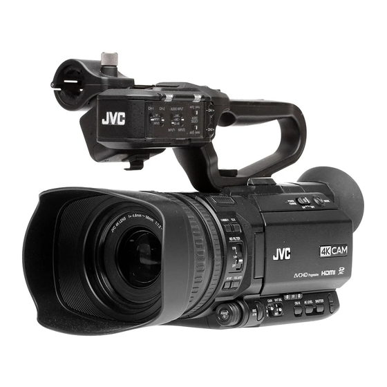
The illustration here shows how the handle unit is attached using the unit supplied.
.
The specifications and appearance of this product are subject to changes for further improvement
without prior notice.
Please check the latest version of the INSTRUCTIONS from the following Mobile User Guide. You can
also download the PDF from the Mobile User Guide.
Mobile User Guide
When you are outside, you can refer to the instructions from your Android phone or iPhone.
http://manual3.jvckenwood.com/pro/mobile/global/
You can view the Mobile User Guide using the browser on your Android phone or iPhone.
For Customer Use:
Enter below the Serial No. which is located
on the body.
Retain this information for future reference.
Model No.
GY-HM250U/GY-HM180U/GY-HM170U
Serial No.
IM 1.05
GY-HM250U(G)/GY-HM250E(G)
GY-HM180U(G)/GY-HM180E(G)
GY-HM170U(G)/GY-HM170E(G)
This manual provides a brief explanation on operating this
camera recorder. For detailed operation methods and camera
settings, please refer to the following Mobile User Guide.
Please read the following before getting started:
Thank you for purchasing this product.
Before operating this unit, please read the
instructions carefully to ensure the best
possible performance.
In this manual, each model number is
described without the last letter (U/E) which
means the shipping destination.
(U: for USA and Canada, E: for Europe)
Only "U" models (GY-HM250U/GY-HM180U/
GY-HM170U) have been evaluated by UL.
B5A-4078-00
Advertisement
Table of Contents

Related Manuals for JVC GY-HM180U


Summary of Contents for JVC GY-HM180U
- Page 1 (U/E) which on the body. means the shipping destination. Retain this information for future reference. (U: for USA and Canada, E: for Europe) Model No. GY-HM250U/GY-HM180U/GY-HM170U Only “U” models (GY-HM250U/GY-HM180U/ Serial No. GY-HM170U) have been evaluated by UL. IM 1.05 B5A-4078-00...
- Page 3 FOR USA These are general IMPORTANT SAFEGUARDS and certain items may not apply to all appliances. IMPORTANT SAFEGUARDS Read these instructions. Keep these instructions. Heed all warnings. Follow all instructions. Do not use this apparatus near water. Clean only with dry cloth. Do not block any ventilation openings.
-
Page 4: Safety Precautions
RISK OF ELECTRIC undesired operation. SHOCK DO NOT OPEN Changes or modifications not CAUTION: approved by JVC could void the TO REDUCE THE RISK OF user’s authority to operate the ELECTRIC SHOCK. equipment. This equipment has been DO NOT REMOVE COVER (OR tested and found to comply with the BACK). - Page 5 POUR CANADA WARNING: TO PREVENT FIRE OR SHOCK HAZARD, DO NOT EXPOSE THIS UNIT TO RAIN OR ATTENTION MOISTURE. RISQUE D’ELECTROCUTION AVERTISSEMENT : POUR EVITER NE PAS OUVRIR LES RISQUES D’INCENDIE OU ATTENTION: D’ELECTROCUTION, NE PAS POUR EVITER TOUT RISQUE EXPOSER L’APPAREIL A LA D’ELECTROCUTION NE PAS PLUIE NI A L’HUMIDITE.
- Page 6 When the equipment is installed in a When using the AC adapter in cabinet or on a shelf, make sure that it areas other than the USA has sufficient space on all sides to allow The provided AC adapter features for ventilation (10 cm (3-15/16") or more automatic voltage selection in the AC on both sides, on top and at the rear).
- Page 7 FOR EUROPE IMPORTANT (for owners in the U.K.) This equipment is in conformity with the Connection to the mains supply in provisions and protection requirements of the United Kingdom. the corresponding European Directives. DO NOT cut off the mains plug from This equipment is designed for professional this equipment.
- Page 8 Battery Pack Dear Customer The supplied battery pack is a lithium-ion This apparatus is in conformance with battery. Before using the supplied battery the valid European directives and pack or an optional battery pack, be sure standards regarding electromagnetic to read the following cautions: compatibility and electrical safety.
- Page 9 Importeur (Alleen EU) Para Retirar a Bateria Recarregável Pressione botão e puxe a bateria para fora. Amsterdamseweg 37, 1422 AC Uithoorn, NEDERLAND GY-HM250U/GY-HM250E Empurre Manufacturer 3-12, Moriya-cho, Kanagawa-ku, Yokohama-shi, Kanagawa, 221-0022, JAPAN GY-HM180U/GY-HM180E GY-HM170U/GY-HM170E Empurre Safety Precautions...
-
Page 10: Table Of Contents
Verifying the Accessories ........ 10 product. Names of Parts ..........11 : Feature available on GY-HM250U/GY- HM250E only. Preparations : Feature available on GY-HM180U/GY- Attaching the Handle Unit ........ 14 HM180E only. : Feature available on Adjusting the Grip Belt ........14 GY-HM170U/GY-HM170E only. -
Page 11: Names Of Parts
Names of Parts o Bottom A Built-in Microphone B Handle Unit G Visibility Adjustment Lever Memo : H Battery The handle unit is detached from the camera I Viewfinder recorder unit in the factory shipment. J Eyepiece For details on attaching the handle unit, please refer to [Attaching the Handle Unit] . - Page 12 B [AF/MF] Focus Selection Button G F E C [ND FILTER] ND Filter Switch D [F.ASSIST/1] Focus Assist/User 1 Button GY-HM180U/GY-HM180E E [TC/2] Time Code/User 2 Button GY-HM170U/GY-HM170E F LCD monitor G J / K Volume Buttons/[+/-] Selection Buttons...
- Page 13 LCD Monitor A Microphone Holder B Microphone Holder Lock Knob C Handle Tally Lamp D Accessory Mounting Screw Hole E Shoe F Handle Unit Fastening Screw G Zoom Lever on Handle H [ZOOM L/M/H] Zoom Speed Switch I [REC/HOLD] Record Trigger Button/Lock Switch Memo : This switch is interlocked with the [REC] button...
-
Page 14: Attaching The Handle Unit
Attaching the Handle Unit Adjusting the Grip Belt The handle unit is detached from the camera Open the pad and adjust the position of the grip belt recorder unit in the factory shipment. accordingly. To use the handle unit, attach it by following the steps below. -
Page 15: Charging The Battery
Charge the battery immediately after purchase or when the battery power is running low. * The battery is not charged when purchased. GY-HM180U/GY-HM180E GY-HM170U/GY-HM170E 1 Hold down the lock button (blue) at the center of the [POWER ON/OFF] switch to set to “OFF”. -
Page 16: Attaching The Hood
Attaching the Hood Estimated Charging and Continuous Operating Times o Charging time SSL-JVC50 (accessory) n : Approx. 4 hrs Attaching the Hood : Approx. 3 hrs 40 BN-VC826 (accessory) m Align the markings on the camera recorder and mins hood; turn the hood in the direction of the arrow * When the [POWER ON/OFF] switch is set to “OFF”... -
Page 17: Configuring The Initial Settings
Configuring the Initial Memo : Settings The menus and messages on the screen of the LCD monitor or viewfinder are displayed in the selected language. When the power is first turned on, the Initial Setting screen for performing the initial settings in the camera recorder appears. -
Page 18: Usable Cards
Usable Cards 4 Press the Set button (R) after confirming the exit screen. The [Initial Setting] screen appears. For U models Format Setting and Usable SD Card Combinations Usable System Format Bit Rate SD Card High- QuickTime 50M (XHQ) UHS-I U3 Initial Setting Speed 35M (UHQ) -
Page 19: Estimated Recordable Time Of Sd Cards
Estimated Recordable o When [Main Menu] B [System] B [Record Set] B [Record Format] B [Format] is set to Time of SD Cards “Exchange” (U model only) System The estimated recordable time is only a guide. Resolution 1080p 720p Differences may occur depending on the SD card Bit Rate in use and the battery condition. -
Page 20: Inserting An Sd Card
Inserting an SD Card 1 Select [System] B [Media] B [Format Media]. This camera recorder comes with two card slots 2 Select the slot of the SD card to be (Slot A and B) for video/audio recording and formatted and press the Set button (R). playback. - Page 21 Clip (Recorded Data) and Clip Name Memo : During formatting, menu operation is When recording is stopped, the images, audio unavailable but you can start recording. and accompanying data which are recorded However, this is only available when a from start to stop are recorded as one “clip” on recordable SD card is inserted in the other slot.
-
Page 22: Shooting
Basic Shooting Shooting Procedures Preparations 1 Press the [REC] button to start recording to the SD card. This camera recorder has two [REC] buttons. Any of the [REC] buttons can be used to start/ stop recording by default. The tally lamp lights up in red during recording. Zoom Operation Adjusting the Focus Memo :... -
Page 23: Miscellaneous Functions For Shooting And Recording Methods
Miscellaneous Functions Recording Methods for Shooting and A Recording using both slots A and B Continuous recording (Series Rec): Recording Methods Enables seamless long hour continuous recordings over the slots. Record simultaneously at the same definition This camera recorder is equipped with various (Dual Rec): functions for shooting. -
Page 24: Playing Recorded Clips
Playing Recorded Clips Audio Output during Playback You can confirm the playback sound from the monitor speaker, or the headphone connected Use the operation buttons on the side control panel to the [x] terminal. When a headphone is of the camera recorder to play back. connected to the [x] terminal, sound cannot be output from the monitor speaker. -
Page 25: Connecting External Devices
Connecting External * Select the output signal in [A/V Set] B [HDMI/SDI Out]. n m Monitor * Select the output signal in [A/V Set] B [HDMI Out]. M To output live or playback video images and * When [Record Format] B [System] is set to audio sound to an external monitor, select the “SD”, only SD-SDI signals are output. -
Page 26: Functions Of Network Connection N
Functions of Network Editing Metadata Planning Metadata Connection n You can access the page for editing the camera recorder’s metadata via a web browser on devices such as a smartphone, tablet terminal, The network function can be operated by or PC, and edit the metadata that is to be applied connecting one of the following adapters to the to clips to be recorded. -
Page 27: Menu Screen Hierarchical Chart
Menu Screen Hierarchical Chart TC/UB... Main Menu... TC Generator Overlay Settings... n TC Preset Layout UB Mode Import User Layout Drop Frame Delete User Layout Type LCD/VF... Output... Shooting Assist... Watermark Marker Settings... Full Screen Graphic... Display Settings... Password Lock VF SW Camera Function... -
Page 28: Basic Operations In Menu Screen
Basic Operations in Menu A [MENU/THUMB] Button Displays the menu screen. The [Main Menu] Screen screen is displayed by default. During normal usage, [Main Menu] is displayed if the previous menu operation Press the [MENU/THUMB] button on the LCD ended at [Main Menu], and [Favorites Menu] monitor to display the menu screen on the LCD if the previous menu operation ended at monitor and viewfinder. -
Page 29: Display Screen
Display Screen A OK Mark Displayed when OK mark has been appended. B Voltage/Battery Power Displays the current status of the power supply Display Screen in Camera Mode in use. Memo : Display 0 screen Displayed in the Display 0 and Display 1 screens This screen displays the event. - Page 30 F Audio Level Meter Memo : Displays the audio levels of CH1 and CH2. This item is not displayed when [LCD/VF] B The V icon appears on the screen when in [Display Settings] B [Media Remain] is set to Manual mode. “Off”.
- Page 31 J AE Lock O AE Level Displayed when the AE function is activated. The U icon is displayed during AE lock. When operated while manual operation is K White Balance Mode disabled, “AE” blinks for about 5 seconds. Displays the current white balance mode. When face detection is enabled and [Face (*****K indicates color temperature) Detect] is set to “AF&AE”, q appears on the...
- Page 32 S Focus Assist V Network Connection Icon n “FOCUS” is displayed when auto focus is The network connection status is displayed activated. when [System] B [Network] is set to “On”. When ACCU-Focus is enabled, “ACCU- This icon is not displayed when “Off” is selected. FOCUS”...
- Page 33 b Dual Rec/Backup Rec Display Y Live streaming mark n “DUAL” is displayed in the Dual Rec mode and When [System] B [Network]/[Settings] B [Live “BACKUP” is displayed in the Backup Rec Streaming Set] B [Live Streaming] is set to mode.
- Page 34 Display Screen in Media Mode A Media Displays the media slot (W or Y) of the Media Display 0 Screen currently played clip. z appears when the write-protect switch of This screen displays the media status or event. It the SD card is set. is also used to display warnings only.
- Page 35 I Information Display K Network Connection Icon n The camera information display turns on and off The network connection status is displayed each time you press the [OIS/6] button. when [System] B [Network] is set to “On”. Camera information display displays only This icon is not displayed when “Off”...
-
Page 36: Status Screen
Status Screen M Event/Warning Display Area Displays error messages. N Media Status This screen allows you to check the current settings. PLAY : Playing To display the status screen, press the STILL : Still picture playback mode [STATUS] button in the normal screen. FWD * : High-speed playback in the The status display differs according to the... -
Page 37: Troubleshooting
Troubleshooting Symptom Action Power does not turn on. Is the AC adapter properly connected? Is the battery charged? Is the power turned on immediately after it is turned off? Make sure to wait for an interval of at least 5 seconds before turning on the power again. - Page 38 Symptom Action Incorrect display on the Is [LCD/VF] B [VF SW] set to “Enable”, and is the viewfinder in use viewfinder. without being pulled out? To use the viewfinder in this setting, pull out the viewfinder. The actual recording time is The recordable time may be shorter depending on the shooting shorter than the estimated conditions or the subject.
-
Page 39: Precautions For Proper Use
Precautions for Proper Power Saving o When this unit is not in use, be sure to set the [POWER ON/OFF] switch to “OFF” in order to reduce power consumption. Maintenance Storage and Usage Locations o Turn off the power before performing any o Allowable ambient temperature and humidity maintenance. - Page 40 o We are not liable for any accidental loss of data Regular Inspection (Maintenance) stored on the SD card. Please back up any o Under normal environment, dust will important data. accumulate on the camera recorder when it is o Make use of the SD card within the prescribed used over a long period.
- Page 41 LCD Monitor and Viewfinder Copyright o The LCD monitor and viewfinder screen are o Any recordings made on this camera recorder manufactured using high-precision technology. that are played back for profit or public preview Black spots may appear on the LCD monitor and may infringe on the rights of the owner of the viewfinder screen, or red, blue, and/or white recordings.
- Page 42 Others Content of this manual o Do not insert objects other than the memory card All rights reserved by JVCKENWOOD into the card slot. Corporation. Unauthorized duplication or o Do not block the vent on the unit. reprinting of this manual, in whole or in part, is Blocking of the vent causes internal heating and strictly prohibited.
-
Page 43: Specifications
Specifications Item Description Φ3.5 mm stereo mini jack [x] terminal Output -18 dBu, 16 K load (reference level at -20 dBFS, and at General maximum headphone volume) [REMOTE] Φ2.5 mm wired remote control Item Description terminal Power DC 12 V [U] terminal Power [DEVICE]... - Page 44 Item Description Item Description HD mode (QuickTime) SD mode (QuickTime) Recording file QuickTime File Format Recording file QuickTime File Format format format Video Video MPEG-4 AVC/H.264, 8 Mbps 720x480/59.94i (U model only), YUV422 MPEG-4 AVC/H.264 50 Mbps 720x576/50i (E model only) mode, XHQ (Max) 1920x1080/59.94p, 59.94i, mode...
-
Page 45: Software License Agreement
Software License Article 3 Conditions for Grant of License Agreement 1. When the User transfers the Product, it may also transfer the license to use the Licensed Software embedded in the Product (including any related materials, updates and upgrades) on condition that The software embedded in the Product (hereinafter no original, copies or related materials continue in the “Licensed Software”) provided by... - Page 46 Article 8 Termination In case the User falls under any of the events described in the following items, the Licensor may immediately terminate this Agreement or claim that the User compensates for the damage incurred by the Licensor due to such event: (1) when the User violated any provision of this Agreement;...
-
Page 47: Important Notice Concerning The Software
Important Notice Users are urged to read the details for the relevant license carefully before using the software concerning the Software component covered by “GPL/LGPL” and embedded in the Product. Since the terms and conditions of individual licenses are provided by parties other than JKC, the original English version Software License Attached to the Product : will be displayed by the Product. - Page 48 B5A-4078-00 © 2021 JVCKENWOOD Corporation...
Need help?
Do you have a question about the GY-HM180U and is the answer not in the manual?
Questions and answers