Advertisement
Quick Links
Advertisement

Subscribe to Our Youtube Channel
Related Manuals for Commell LP-172D


Summary of Contents for Commell LP-172D
- Page 1 LP-172 Pico-ITX User’s Manual 2012/03/27 Version:1.0...
- Page 2 LP-172 User’s Manual Copyright Copyright 2012. All rights reserved. This document is copyrighted and all rights are reserved. The information in this document is subject to change without prior notice to make improvements to the products. This document contains proprietary information and protected by copyright. No part of this document may be reproduced, copied, or translated in any form or any means without prior written permission of the manufacturer.
-
Page 3: Packing List
(OALDC-B) Dual COM PORT cable (OALES-BKU2NB) Audio Cable x 1 PS/2 keyboard & mouse cable x 1 (OALPJ-HDUNB) (OALPS2/MK) LP-172N Heatsink x 1 LP-172D Heatsink with Fan x 1 (OHS-172) (OHS-172F) Printed Matters: Driver CD x 1 (Including User’s Manual) - Page 4 LP-172 User’s Manual Index Chapter 1 <Introduction> ..................6 1.1 <Product Overview>....................6 1.2 <Product Specification> ..................7 1.3 <Mechanical Drawing> ..................9 1.4 <Block Diagram> ....................10 Chapter 2 <Hardware Setup>................11 2.1 <Connector Location> ..................11 2.2 <Jumper Reference>....................13 2.3 <Connector Reference> ..................14 2.3.1 <Internal Connector> ................14 2.3.2 <External Connector>...
- Page 5 LP-172 User’s Manual A.2 <CRT Port>......................34 A.3 <LAN Port> ......................34 A.4 <LAN LED Port> ....................35 A.5 <LPC Port>......................35 Appendix B <Flash BIOS> ................36 B.1 BIOS Auto Flash Tool ..................36 B.2 Flash Method.......................36 Appendix C <System Resources> ..............37 C.1 <I/O Port Address Map> ..................37 C.2 <Memory Address Map>...
- Page 6 LP-172 User’s Manual (This page is left for blank)
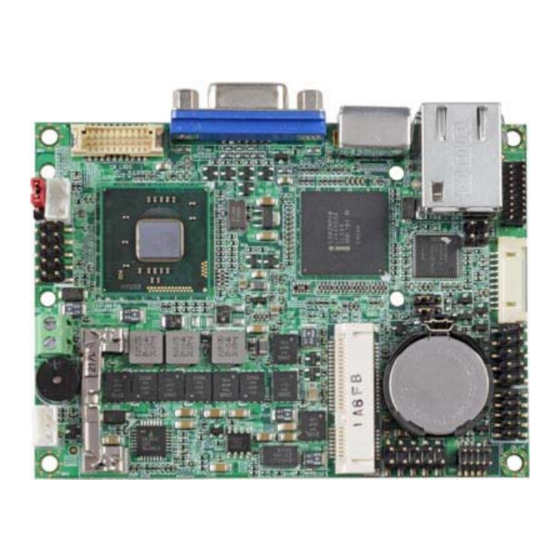
- Page 7 LP-172 User’s Manual Chapter 1 <Introduction> 1.1 <Product Overview> LP-172 is the PICO-ITX miniboard with Intel® Atom™ CedarTrail Processor with optional D2700 or N2800 platform, Intel® NM10, integrated Intel® GMA 3650 graphics, DDR3 SO-DIMM memory, Realtek ALC888 HD Codec audio and one Intel® 82583V Giga LAN.
- Page 8 LP-172 User’s Manual 1.2 <Product Specification> General Specification Form Factor PICO-ITX miniboard Intel® Atom™ CedarTrail Processor with optional D2700(2.13GHz) or N2800(1.86GHz) Memory 1 x 204-pin DDR3 800/1066 SO-DIMM SDRAM up to 4G Chipset Intel® NM10 Watchdog Timer System reset programmable watchdog timer with 1 ~ 255 sec./min.
- Page 9 LP-172 User’s Manual Ordering Code LP-172D Support Intel® Atom™ CedarTrail D2700 processor with onboard VGA, 18 and 24-bit LVDS, Audio, Giga LAN, USB2.0 .SATAII, PCIE mini card LP-172N Support Intel® Atom™ CedarTrail N2800 processor with onboard VGA, 18-bit LVDS, Audio, Giga LAN, USB2.0 .SATAII, PCIE mini card...
- Page 10 LP-172 User’s Manual 1.3 <Mechanical Drawing>...
- Page 11 LP-172 User’s Manual 1.4 <Block Diagram> DDR3 SO-DIMM 4GB max. Intel Atom CRT / LVDS D2700/N2800 PCIE Mini card HD Audio Intel 4 x USB port NM10 Giga LAN 1 x SATA 2 x Serial Port PS2 KB/MS W83627DHG-P...
- Page 12 LP-172 User’s Manual Chapter 2 <Hardware Setup> 2.1 <Connector Location> CPUFAN CN_DDP CN_COM1/2 JFRNT CN_SATA DC_IN CN_USB1 SYSFAN CN_LPC MINI_CARD CN_USB2 CN AUDIO...
- Page 13 LP-172 User’s Manual CN_INV DC_OUT SO-DIMM LP-172 RJ45...
- Page 14 LP-172 User’s Manual 2.2 <Jumper Reference> Jumper Function JRTC CMOS Operating/Clear Setting AT/ATX Mode Setting JVLCD LCD Panel Voltage Setting JVLCD JRTC...
- Page 15 LP-172 User’s Manual 2.3 <Connector Reference> 2.3.1 <Internal Connector> Connector Function Remark SO-DIMM 204 -pin DDR3 SO-DIMM SDRAM slot CN_SATA 10-pin SATA Cable connector MINI_CARD PCIE mini card socket CN_INV 5-pin LCD inverter connector CN_USB1/2 5 x 2-pin USB connector CN_AUDIO 5 x 2-pin audio connector CN_LPC...
- Page 16 LP-172 User’s Manual 2.4 <Memory Setup> The board provides one 204-pin DDR3 SO-DIMM to support DDR3 800/1066 memory modules up to 4GB. SO-DIMM...
- Page 17 LP-172 User’s Manual 2.5 <CMOS & ATX Setup> The board’s data of CMOS can be setting in BIOS. If the board refuses to boot due to inappropriate CMOS settings, please remove battery to clear (reset) the CMOS to its default values. JRTC Battery The board has a jumper to switch AT power mode (automatic power on) or standard...
- Page 18 LP-172 User’s Manual 2.6 <SATA Interface> Based on Intel NM10, the board provides one Serial ATAII interfaces with up to 300MB/s of transfer rate. CN_SATA DC_OUT...
- Page 19 LP-172 User’s Manual 2.7 <LAN Interface> The Intel® 82583V supports triple speed of 10/100/1000Base-T, with IEEE802.3 compliance and Wake-On-LAN supported.
- Page 20 LP-172 User’s Manual 2.8 <Onboard Display Interface> Based on Intel Atom CedarTrail Processor chipset with built-in Intel® integrated extreme GMA 3650, the board provides one DB15 connector on real external I/O port, and LVDS interface with 5-pin LCD backlight inverter connector. The board provides dual display function with clone mode and extended desktop mode for CRT and LVDS.
- Page 21 LP-172 User’s Manual 2.8.2 <CN_LVDS> The board provides one 20-pin LVDS connector for 18 bit single channel panel, with one LCD backlight inverter connector and one jumper for panel voltage setting. CN_LVDS JVLCD CN_INV...
- Page 22 LP-172 User’s Manual Connector: CN_INV Type: 5-pin Inverter power connector Connector model: molex_53261-5pin Description +3.3V CTLBKL Enable Jumper: JVLCD Type: 3-pin Power select jumper Description +3.3V Default: 2-3 Connector: CN_LVDS Type: onboard 20-pin connector for LVDS connector Connector model: HIROSE DF13-20DP-1.25V Signal Signal LCDVCC...
- Page 23 LP-172 User’s Manual LCD Installation Guide: Preparing the LP-172, LCD panel and the backlight inverter You would need a LVDS type cable. Panel side Board side For sample illustrator only To connect all of the devices well.
- Page 24 LP-172 User’s Manual After setup the devices well, you need to select the LCD panel type in the BIOS. The panel type mapping is list below: LP-172 BIOS panel type selection form On board Single channel LVDS 18bit Output format 640 x 480 800 x 600 1024 x 768...
- Page 25 LP-172 User’s Manual 2.9 <Onboard Audio Interface> The board provides the onboard high definition audio with Realtek ALC888 Connector: CN_AUDIO Type: 10-pin (2 x 5) 1.27mm x 2.54mm-pitch header Description Description MIC2_L AGND MIC2_R AVCC FP_OUT_R MIC2_JD SENSE_B FP_OUT_L LINE2_JD CN_AUDIO...
- Page 26 LP-172 User’s Manual 2.10 <USB2.0 Interface> Based on Intel® NM10 FCH, the board provides 4 USB2.0 ports. The USB2.0 interface provides up to 480Mbps of transferring rate. Interface USB2.0 Controller NM10 Transfer Rate Up to 480Mb/s Output Current 500mA CN_USB1 CN_USB2 Connector: CN_USB Type: 10-pin (5 x 2) header for USB Port...
- Page 27 LP-172 User’s Manual 2.11 <Serial Port Jumper Setting > The board provides two RS232 serial ports Connector: CN_COM1/2 Type: 20-pin (5 x 2) 1.27mm x 2.54mm-pitch header for COM1/2 Description Description MDCD1- MSIN1- MSO1- MDTR1- MDSR1- MRTS1- MCTS1- MRI1- MDCD2- MSIN2- MSO2- MDTR2-...
- Page 28 LP-172 User’s Manual 2.12 <Power & FAN Connector > The board requires DC input with 2-pin header, the input voltage range is from 5V for the input current, please take a reference of the power consumption report on appendix. 2.12.1 <Power Input> Connector: DC_IN Type: 2-pin header Description...
- Page 29 LP-172 User’s Manual 2.12.2 <Power Output> Connector: DC_OUT Type: 6-pin connector for +5V output Pin Description Pin Description Pin Description Ground Ground Note: Maximum output current 5V/1A DC_OUT...
- Page 30 LP-172 User’s Manual 2.12.3 <Fan Connector> Connector: SYSFAN Type: 3-pin fan wafer connector Connector model: 2001-WS-03-LF Description Description Description Ground CSFAN Connector: CPUFAN Type: 3-pin fan wafer connector Connector model: 2001-WS-03-LF Description Ground P1FAN CPUFAN SYSFAN...
- Page 31 LP-172 User’s Manual 2.13 <Indicator and Switch> The JFRNT provides front control panel of the board, such as power button, reset and beeper, etc. Please check well before you connecting the cables on the chassis. Connector: JFRNT Type: onboard 10-pin (2 x 5) 2.54-pitch header Function Signal Signal...
- Page 32 LP-172 User’s Manual (This Page is Left For Blank)
- Page 33 LP-172 User’s Manual Chapter 3 <BIOS Setup> The motherboard uses the Phoenix BIOS for the system configuration. The Phoenix BIOS in the single board computer is a customized version of the industrial standard BIOS for IBM PC AT-compatible computers. It supports Intel® x86 and compatible CPU architecture based processors and computers.
- Page 34 LP-172 User’s Manual (This Page is Left for Blank)
- Page 35 LP-172 User’s Manual Appendix A <I/O Port Pin Assignment> A.1 <SATA Port> Connector: SATA Type: 10-pin header for SATA Port Description Description Ground Ground Ground Ground A.2 <CRT Port> Connector: CRT Type: 15-pin D-sub female connector on rear panel Description Description Description Ground...
- Page 36 LP-172 User’s Manual A.4 <LAN LED Port> Connector: JSPD1 Type: 2-pin header for LAN Speed LED connector RJ45 connector with LED on rear panel When Lan speed 10/100Mbps Description LED- LED+ When Lan speed 1Gbps Description LED+ LED- Connector: JACT Type: 5-pin header for LAN Activity LED connector Description LED-...
-
Page 37: Bios Auto Flash Tool
The board is based on Award BIOS and can be updated easily by the BIOS auto flash tool. You can download the tool online at the address below: http://www.phoenix.com/en/home/ http://www.commell.com.tw/Support/Support_SBC.htm File name of the tool is “Pflash.exe”, it’s the utility that can write the data into the BIOS flash ship and update the BIOS. - Page 38 LP-172 User’s Manual Appendix C <System Resources> C.1 <I/O Port Address Map>...
- Page 39 LP-172 User’s Manual...
- Page 40 LP-172 User’s Manual C.2 <Memory Address Map>...
- Page 41 LP-172 User’s Manual C.3 <System IRQ Resources>...
- Page 42 LP-172 User’s Manual...
- Page 43 LP-172 User’s Manual...
- Page 44 LP-172 User’s Manual Appendix D <Watch Dog timer Setting> The watchdog timer makes the system auto-reset while it stops to work for a period. The integrated watchdog timer can be setup as system reset mode by program. Timeout Value Range - 1 to 255 - Second or Minute Program Sample...
Need help?
Do you have a question about the LP-172D and is the answer not in the manual?
Questions and answers