Advertisement
Quick Links
Advertisement

Related Manuals for Commell LP-178


Summary of Contents for Commell LP-178
- Page 1 LP-178 Pico-ITX Motherboard User’s Manual Edition 1.1 2019/09/18...
- Page 2 LP-178 User’s Manual Copyright Copyright 2019, all rights reserved. This document is copyrighted and all rights are reserved. The information in this document is subject to change without prior notice to make improvements to the products. This document contains proprietary information and protected by copyright. No part of this document may be reproduced, copied, or translated in any form or any means without prior written permission of the manufacturer.
-
Page 3: Packing List
LP-178 User’s Manual Packing List: Please check the package content before you starting using the board. 1 x LP-178 Pico-ITX Motherboard Including Cooler Fan) 1 xDC Input Power Cable 1 x SATA & SATA Power Cable (OALDC-B / 1040513) (OALSATA22B-PM15SH15 / 1040512) 1 x Dual COM Cable 1 xUSB2.0 cable... - Page 4 LP-178 User’s Manual Index Chapter 1 <Introduction>............... 5 1.1 <Product Overview>............5 1.2 <Product Specification> ............6 1.3 <Block Diagram>..............7 Chapter 2 <Hardware setup>............8 2.1 <Connector Location and Reference> ........ 8 2.1.1 <Internal connectors list> ..........9 2.1.2 <External connectors list>.........9 2.2 <Jumper Location and Reference>...
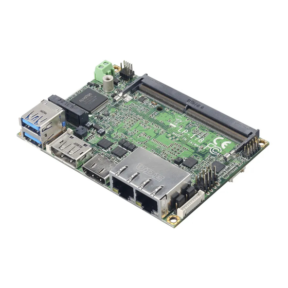
- Page 5 LP-178 User’s Manual Chapter 1 <Introduction> 1.1 <Product Overview> LP-178 is a Motherboard which supports 8th Generation Intel® Core™ U-Series Pico-ITX processors, integrated HD Graphics, DDR4 memory, Realtek High Definition Audio, Intel Gigabit LAN, USB3.1 Gen2, SATA3 with AHCI function for a system.
-
Page 6: Mechanical And Environmental
LP-178 User’s Manual 1.2 <Product Specification> System Intel® Whiskey Lake Processor Processor FCBGA1528 package 1 x DDR4 SO-DIMM 2400 MHz up to 16GB (Note1), Memory Support Non-ECC, unbuffered memory Watchdog Timer Generates a system reset with internal timer for 1min/s ~ 255min/s... - Page 7 LP-178 User’s Manual 1.3 <Block Diagram> DDR4 2400 SO-DIMM Header for LVDS or VGA PTN3460 Whiskey Lake Processor HDMI I219 I210 1 x SATA 2 x USB3.1 Gen2 1 x M.2 (Key E) 2 x USB2.0 SMBus ALC262 2 x RS232...
- Page 8 LP-178 User’s Manual Chapter 2 <Hardware setup> 2.1 <Connector Location and Reference> CN_AUDIO DDR4 DC_IN JFRNT M.2 (E KEY) CN_USB CN_LVDS CN_BAT CN_LPC CN_SMBUS CPUFAN CN_COM1/2 SYSFAN DC_OUT SATA_PWR CN_SATA...
- Page 9 LP-178 User’s Manual HDMI RJ-45-1 RJ-45-2 2.1.1 <Internal connectors list> Connector Function DDR4 260-pin DDR4 SO-DIMM slot CN_SATA 10-pin Serial ATA3 connector CN_AUDIO 5 x 2-pin audio pin header CN_LPC 11-pin LPC pin header CN_LVDS 11-pin connector (For ADP-3460E or ADP-3355)
- Page 10 LP-178 User’s Manual 2.2 <Jumper Location and Reference> 2.2.1 <Jumper list> JRTC Jumper Function Power mode select JRTC CMOS Normal/Clear Setting -10-...
- Page 11 LP-178 User’s Manual 2.2.2 <Clear CMOS and Power on type selection> JRTC JRTC: Clear CMOS data jumper Jumper settings Function Clear CMOS Normal (Default) JAT: AT/ATX mode select jumper Jumper settings Function AT mode ATX mode (Default) -11-...
- Page 12 LP-178 User’s Manual 2.3 <Installing the Memory> LP-178 has 260-pin DDR4 SODIMM support up to 16GB of memory capacity and 1.2 Voltage. Only Non-ECC memory is supported. In the process, the board must be powered off. 1. Put the memory tilt into the slot. Note the Memory notch key aligned slot key.
- Page 13 LP-178 User’s Manual 2.4 <I/O interface> 2.4.1 <Serial ATA interface> CN_SATA: SATA3 10-pin connector Signal CN_SATA -13-...
- Page 14 LP-178 User’s Manual 2.4.2 <Ethernet interface> The board provides I210-AT and I219-LM Gigabit Ethernet which support Wake on LAN. It supports Intel® AMT 12.0 feature on I219-LM. (Note that the CPU must support vPro technology.) I219 I210 2.4.3 <Display interface>...
- Page 15 LP-178 User’s Manual CN_LVDS: 11-pin connector Signal Signal eDP_0+ eDP_0- eDP_1+ eDP_1- eDP_AUX+ eDP_AUX- 3.3V There are two modules ADP-3355 and ADP-3460E, you can choose the one to support VGA or LVDS, please refer Appendix E. -15-...
- Page 16 LP-178 User’s Manual 2.4.4 <Serial Port interface> CN_COM1/2 CN_COM1/2: RS232 20-pin connector Signal Signal DCD1 RXD1 TXD1 DTR1 DSR1 RTS1 CTS1 DCD2 RXD2 TXD2 DTR2 DSR2 RTS2 CTS2 -16-...
- Page 17 LP-178 User’s Manual 2.4.5 <USB interface> CN_USB USB3.1 Gen2 CN_USB: Front panel USB2.0 10-pin header (Pitch 2.54mm) Signal Signal 5VSB 5VSB DATA0- DATA1- DATA0+ DATA1+ -17-...
- Page 18 LP-178 User’s Manual 2.4.6 <Audio interface> CN_AUDIO CN_USB2-2 CN_AUDIO: Front panel audio 10-pin header (Pitch 1.27mm x 2.54mm) Signal Signal MIC_L MIC_R FP_OUT_R MIC_DETECT SENSE FP_OUT_L FP_OUT_DETECT -18-...
- Page 19 LP-178 User’s Manual 2.4.7 <Expansion slot> M.2 (E KEY) M2 (Key E) with 2 x PCI Express x1 support WI-FI and Bluetooth Module -19-...
- Page 20 LP-178 User’s Manual 2.4.8 <Front panel switch and indicator> JFRNT JFRNT: Front panel switch and indicator 10-pin header Signal Signal Power_ON- Power_ON+ Speaker- Speaker+ HDD_LED- HDD_LED+ Power_LED- Power_LED+ Reset+ Reset- -20-...
- Page 21 LP-178 User’s Manual 2.4.9 <SMBus and Other Interface> CN_LPC CPUFAN SYSFAN CN_SMBus -21-...
- Page 22 LP-178 User’s Manual CN_SMBus: SMBus 5-pin connector Signal SMBDAT SMBCLK CPUFAN: CPU cooler fan 4-pin connector Signal Sensor Control SYSFAN: System cooler fan 4-pin connector Signal Sensor Control CN_LPC: LPC 11-pin header Signal -LFRAME LAD3 LAD2 LAD1 LAD0 3.3V SERIRQ...
- Page 23 LP-178 User’s Manual 2.5 <Power supply> 2.5.1 <Power input> DC_IN DC_IN: Terminal block 2-pin power connector Signal Signal ±5% 2.5.2 <Power output> DC_OUT DC_OUT: power 6-pin connector Signal -23-...
- Page 24 LP-178 User’s Manual SATA_PWR SATA_PWR: power 6-pin connector Signal -24-...
- Page 25 LP-178 User’s Manual Appendix A <Flash BIOS> A.1 <Flash tool> The board is based on Insyde BIOS and can be updated easily by the BIOS auto flash tool. You can download the tool online at the address below: FPT Tool The tool’s file name is “FPT.exe”, it’s the utility that can write the data into the...
- Page 26 LP-178 User’s Manual Appendix B <LCD Panel Type select> According your panel, it needs to select the correct resolution in the BIOS. If there is no fit your panel type, please feedback for us to make OEM model. Find the setting from Front Page->...
- Page 27 LP-178 User’s Manual LVDS configurationLCD Control There are 16 resolutions in LCD Panel Type. (For Dual boot and Legacy boot) -27-...
- Page 28 LP-178 User’s Manual Appendix C <Programmable Watch Dog Timer> The watchdog timer makes the system auto-reset while it stops to work for a period. The integrated watchdog timer can be setup as system reset mode by program. You can select Timer setting in the BIOS, after setting the time options, the system will reset according to the period of your selection.
- Page 29 LP-178 User’s Manual Program sample Watchdog timer setup as system reset with 5 second of timeout -o 4E 87 ;enter configuration -o 4E 87 -o 4E 07 -o 4F 08 ;select Logical Device -o 4E 30 -o 4F 01 ; activate WDTO# function...
- Page 30 LP-178 User’s Manual Appendix D <Hardware Monitor> Find the setting from AdvancedSuper IO ConfigurationHardware Monitor -30-...
- Page 31 LP-178 User’s Manual Appendix E <Setup ADP-3355,ADP-3460E> LP-178 have a Header for VGA or LVDS , it’s no need install extra driver. You have to connect SMBus cable to LP-178 (Please see the picture below), then LVDS Configuration in BIOS Setup menu can work.
-
Page 32: Contact Information
Taiwan Commate computer Inc. 19F., NO.94, Sec. 1, Xintai 5 Rd., Xizhi Dist., New Taipei Address City 22102, Taiwan. +886-2-26963909 Website www.commell.com.tw info@commell.com.tw (General information) E-mail tech@commell.com.tw (Technical Support) Commell is a brand name of Taiwan Commate computer Inc. -32-...
Need help?
Do you have a question about the LP-178 and is the answer not in the manual?
Questions and answers