Table of Contents
Advertisement
Quick Links
Advertisement
Table of Contents

Related Manuals for Commell LP-177


Summary of Contents for Commell LP-177
- Page 1 LP-177 Pico-ITX Motherboard User’s Manual Edition 1.0 2017/04/20...
- Page 2 LP-177 User’s Manual Copyright Copyright 2017, all rights reserved. This document is copyrighted and all rights are reserved. The information in this document is subject to change without prior notice to make improvements to the products. This document contains proprietary information and protected by copyright. No part of this document may be reproduced, copied, or translated in any form or any means without prior written permission of the manufacturer.
-
Page 3: Packing List
Packing List: Please check the package content before you starting using the board. 1 x SATA Cable (OALSATA22B-PM15SH15) / (1040512) 1 x LP-177 Motherboard 1 xDC Input Power Cable 1 x PS/2 Keyboard & Mouse cable (OALDC-B / 1040513) (OALPS2/KM / 1040131) 1 x Dual COM cable 1 xUSB2.0 cable... -
Page 4: Table Of Contents
LP-177 User’s Manual Index Chapter 1 <Introduction>..............4 1.1 <Product Overview>............4 1.2 <Product Specification> ............5 1.3 <Block Diagram>..............6 Chapter 2 <Hardware setup> ............7 2.1 <Connector Location and Reference> ........ 7 2.1.1 <Internal connectors list> ..........8 2.1.2 <External connectors list>.........8 2.2 <Jumper Location and Reference>... -
Page 5: Chapter 1
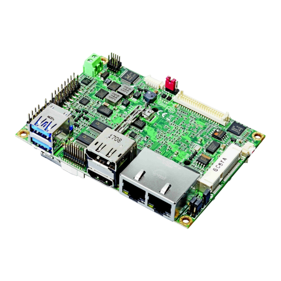
LP-177 User’s Manual Chapter 1 <Introduction> 1.1 <Product Overview> LP-177 is pico Motherboard which is design based on Intel® Celeron® Processor N3350, and Intel® Pentium® Processor N4200 (Apollo Lake SoC), delivering outstanding compute, graphical, and media performance while operating in an extended range of thermal conditions. -
Page 6: Product Specification
LP-177 User’s Manual 1.2 <Product Specification> System Intel® Apollo Lake Series Processor N3350/ N4200, Processor FCBGA1296 package Chipset Apollo Lake SoC 1 x DDR3L DIMM 1866 MHz up to 8GB, Memory Support Non-ECC, unbuffered memory only Watchdog Timer Generates a system reset with internal timer for 1min/s ~ 255min/s... -
Page 7: Block Diagram
LP-177 User’s Manual 1.3 <Block Diagram> PTN3460 DDR3L Channel A SO-DIMM 1 x LVDS PCIe x2 2 x I210-AT Apollo Lake 1 x DisplayPort PCIe x1 MiniPCIe 1 x HDMI / mSATA SATA3 SATA3 1 x SATA3 SPI Flash USB3.0 2 x USB3.0... -
Page 8: Chapter 2
LP-177 User’s Manual Chapter 2 <Hardware setup> 2.1 <Connector Location and Reference> CN_INV CN_LVDS CN_AUDIO 5V_IN CN_BAT MINI_CARD JFRNT CN_PS2 CN_USB CN_COM1/2 CN_LPC CN_SATA SO-DIMM DC_OUT CPUFAN SYSFAN CN_SMBUS... -
Page 9: Internal Connectors List
LP-177 User’s Manual DisplayPort USB3.0 HDMI RJ-45 RJ-45 2.1.1 <Internal connectors list> Connector Function SO-DIMM 204-pin DDR3L SO-DIMM slot CN_SATA 10-pin Serial ATA3 connector CN_AUDIO 5 x 2-pin audio pin header CN_LPC 10 pin LPC pin header CN_LVDS 20 x 2-pin LVDS connector... -
Page 10: Jumper Location And Reference
LP-177 User’s Manual 2.2 <Jumper Location and Reference> JVLCD JMSATA JRTC JAT 2.2.1 <Jumper list> Jumper Function Power mode select JRTC CMOS Normal/Clear Setting JVLCD Panel Voltage Setting JMSATA MiniCard mSATA Setting 2.2.2 <Clear CMOS and Power on type selection>... -
Page 11: Installing The Memory
LP-177 User’s Manual 2.3 <Installing the Memory> In the process, the board must be powered off. 1. Put the memory tilt into the slot. Note the Memory notch key aligned slot key. 2. Then press down till lock into the mounting notch. -
Page 12: I/O Interface
LP-177 User’s Manual 2.4 <I/O interface> 2.4.1 <Serial ATA interface> CN_SATA: SATA3 10-pin connector Signal CN_SATA 2.4.2 <Ethernet interface> The board provide I210-AT Gigabit Ethernet which supports WOL on rear I/O. Find the setting from Front PageSetup utility AdvancedSouth Cluster Configuration Miscellaneous Confuguration... -
Page 13: Display Interface
LP-177 User’s Manual 2.4.3 <Display interface> Based on the Apollo Lake SoC with built-in HD Graphics, the DisplayPort1.2 up to 4096x2160 @ 60Hz on rear I/O.About the internal Display, the HDMI1.4b resolution up to 3840x2160 @ 30Hz and LVDS (PTN3460) up to 1920x1200 @ 60Hz support 18/24-bit color depth and single/dual channel. - Page 14 LP-177 User’s Manual CN_LVDS: LVDS 40-pin connector ( Model: HIROSE DF13-40DP-1.25V compatible Signal Signal Set by JVLCD Set by JVLCD Detect (Active low) B_LVDS_0- A_LVDS_0- B_LVDS_0+ A_LVDS_0+ B_LVDS_1- A_LVDS_1- B_LVDS_1+ A_LVDS_1+ B_LVDS_2- A_LVDS_2- B_LVDS_2+ A_LVDS_2+ B_LVDS_3- A_LVDS_CLK- B_LVDS_3+ A_LVDS_CLK+ B_LVDS_CLK-...
-
Page 15: Serial Port Interface
LP-177 User’s Manual 2.4.4 <Serial Port interface> CN_COM1/2 CN_COM1/2: RS232 20-pin header (Pitch 1.27mm x 2.54mm) Signal Signal DCD1 RXD1 TXD1 DTR1 DSR1 RTS1 CTS1 DCD2 RXD2 TXD2 DTR2 DSR2 RTS2 CTS2 -14-... -
Page 16: Usb Interface
LP-177 User’s Manual 2.4.5 <USB interface> CN_USB USB3.0 CN_USB: Front panel USB2.0 10-pin header (Pitch 2.54mm) Signal Signal 5VSB 5VSB DATA0- DATA1- DATA0+ DATA1+ -15-... -
Page 17: Audio Interface
LP-177 User’s Manual 2.4.6 <Audio interface> CN_AUDIO CN_AUDIO: Front panel audio 10-pin header (Pitch 1.27mm x 2.54mm) Signal Signal MIC_L MIC_R 3.3V FP_OUT_R MIC_DETECT SENSE FP_OUT_L FP_OUT_DETECT -16-... -
Page 18: Expansion Slot
LP-177 User’s Manual 2.4.7 <Expansion slot> MINI_CARD JMSATA MINI_CARD support mSATA by JMSATA MINI_CARD have some special design to compatible our mini-PCIe card. (ex: MPX-574D2, MPX-210D2 etc) JMSATA: Setting MINI_CARD to support PCIe/mSATA Jumper settings Function Support mSATA Normal operation (Default) -
Page 19: Front Panel Switch And Indicator
LP-177 User’s Manual 2.4.8 <Front panel switch and indicator> JFRNT JFRNT: Front panel switch and indicator 10-pin header (Pitch 2.54mm) Signal Signal Power_ON- Power_ON+ Speaker- Speaker+ HDD_LED- HDD_LED+ Power_LED- Power_LED+ Reset+ Reset- -18-... -
Page 20: Other Interface
LP-177 User’s Manual 2.4.9 <Other interface> CN_PS2 CN_LPC SYSFAN CPUFAN CN_SMBUS -19-... - Page 21 LP-177 User’s Manual CN_LPC: LPC 10-pin header (Pitch 2.00mm) Signal Signal -LFRAME LAD3 LAD2 LAD1 LAD0 3.3V SERIRQ CN_PS/2: PS/2 10-pin header (Pitch 2.54mm) Signal Signal KB_DATA M_DATA KB_CLK M_CLK CN_SMBUS: SMBus 5-pin connector Signal SMBDAT SMBCLK CPUFAN: CPU cooler fan 4-pin connector...
-
Page 22: Power Supply
LP-177 User’s Manual 2.5 <Power supply> 2.5.1 <Power input> 5V_IN 5V_IN: Terminal Block 2-pin power connector Signal Signal Power in (5V ONLY) 2.5.2 <Power output> DC_OUT DC_OUT: SATA power 6-pin connector Signal Signal -21-... -
Page 23: Appendix A
The board is based on Insyde BIOS and can be updated easily by the BIOS auto flash tool. You can download the tool online at the address below: LP-177 DOS reflash tool A.2 Flash Method 1. Please make a bootable UFD which can boot into DOS enviroment. -
Page 24: Appendix B
LP-177 User’s Manual Appendix B <LCD Panel Type select> According your panel, it need to select the correct resolution in the BIOS. If there is no fit your panel type, please feedback for us to make OEM modol. Find the setting from Fornt page----->... - Page 25 LP-177 User’s Manual There are 16 resolutions in Panel Number. BIOS panel type selection form (BIOS Version:1.0) Single / Dual channel Single / Dual channel Type Type Auto 1366 x 768 640 x 480 1680 x 1050 800 x 600...
-
Page 26: Appendix C
LP-177 User’s Manual Appendix C <Programmable Watch Dog Timer> Timeout value range 1 to 255 Minute and Second Program sample Watchdog timer setup as system reset with 5 second of timeout -o 4E 87 ;enter configuration -o 4E 87 -o 4E 07 -o 4F 08 ;select Logical Device... -
Page 27: Appendix D
LP-177 User’s Manual Appendix D <Install Heat Spreader > 1.Install DDR3L SO-DIMM memory 2.Tear two plastic films carefully -26-... - Page 28 LP-177 User’s Manual 3.Put LP-176 on the heat spreader 4.Align the screw holes -27-...
-
Page 29: Appendix E
LP-177 User’s Manual 5.Tighten two screws. The washer is easy broken, so don’t lock too tight. Appendix E <Setup ADP-3355, ADP-3460> LP-177T Series have a CRT or 2nd LVDS, it’s no need install extra driver. For further information, please refer to the manual. -
Page 30: Appendix F
LP-177 User’s Manual Appendix F <SuperIO Setting> Press Delete to enter BIOS Setup menu On Front Page screen, click Setup Utility On Advenced screen, click SIO NUVOTON6106D There are 5 functions in the page. 1.WDT(Watch Dog Timer) 2.Power Loss setting 3.Hardware monitor... -
Page 31: Contact Information
Taiwan Commate computer Inc. 19F., NO.94, Sec. 1, Xintai 5 Rd., Xizhi Dist., New Taipei Address City 22102, Taiwan. +886-2-26963909 +886-2-26963911 Website www.commell.com.tw info@commell.com.tw (General infomation) E-mail tech@commell.com.tw (Technical Support) Commell is a brand name of Taiwan Commate computer Inc. -30-...
Need help?
Do you have a question about the LP-177 and is the answer not in the manual?
Questions and answers