Table of Contents
Advertisement
Quick Links
Advertisement
Table of Contents

Related Manuals for Commell Pico-ITX LP-171


Summary of Contents for Commell Pico-ITX LP-171
- Page 1 LP-171 Pico-ITX User’s Manual Edition 1.2 2015/06/16...
- Page 3 Trademark All trademarks are the property of their respective holders. Any questions please visit our website at http://www.commell.com.tw...
-
Page 4: Packing List
LP-171 User’s Manual Packing List: Please check the package content before you starting using the board. Hardware: LP-171 PICO-ITX“ Miniboard x 1 Cable Kit: DC_IN Power Cable x 1 (OALDC-3) Audio Cable x 1 (OALPJ-HDUNB) PS/2 keyboard & mouse Cable x 1 (OALPS2/MK) Dual COM PORT Cable x 1 (OALES-BKU2NB) - Page 5 LP-171 User’s Manual Index Chapter 1 <Introduction> ................. 6 1.1 <Product Overview>....................6 1.2 <Product Specification> ..................7 1.3 <Mechanical Drawing> ..................9 1.4 <Block Diagram> ....................10 Chapter 2 <Hardware Setup>................. 11 2.1 <Connector Location> ..................11 2.2 <Jumper Reference>....................13 2.3 <Connector Reference> ..................14 2.3.1 <Internal Connector>...
- Page 6 LP-171 User’s Manual A.1 <LPC Port> ......................34 A.2 < CRT Port > ...................... 34 A.3 <LAN Port>......................34 Appendix B <Flash BIOS>................35 B.1 BIOS Auto Flash Tool..................35 B.2 Flash Method ...................... 35 Appendix C <System Resources> ..............36 C.1 <I/O Port Address Map>..................
- Page 7 LP-171 User’s Manual (This page is left for blank)
-
Page 8: Chapter 1
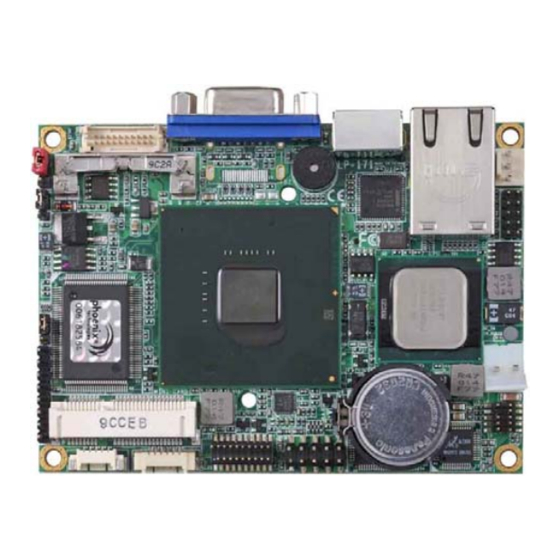
LP-171 User’s Manual Chapter 1 <Introduction> 1.1 <Product Overview> LP-171 is the PICO-ITX miniboard, with Intel® Atom Z510P processor for 400 MHz front side bus, Intel® US15WP SCH, integrated GMA500 graphics, DDR2 SO-DIMM memory, Realtek HD Audio, CF and one Intel® 82574L Gigabit LAN. Intel®... -
Page 9: Product Specification
LP-171 User’s Manual 1.2 <Product Specification> General Specification Form Factor PICO-ITX miniboard Intel® Atom™ Z510P processor 1.1GHz Package type: 437pin FCBGA8 with an IHS, Front side bus: 400MHz Memory 1 x 200-pin DDR2 SO-DIMM SDRAM up to 2GB Unbufferred, none-ECC memory supported only *Memory chip with width x16 bits is strongly recommended! Chipset Intel®... - Page 10 Same as LP-171QT but without VGA, support 24bit dual channel LVDS by MPX-SDVOX ( Note : Onboard MIni-PCIe socket support MPX-SDVOX only ) The specifications may be different as the actual production. For further product information please visit the website at http://www.commell.com.tw...
-
Page 11: Mechanical Drawing
LP-171 User’s Manual 1.3 <Mechanical Drawing> Unit: inch... -
Page 12: Block Diagram
LP-171 User’s Manual 1.4 <Block Diagram> DDR2 SODIMM 2GB max. PCIE mini card socket USB port 24bit Single Channel LVDS Compact Flash CRT / DVI HD Audio W83627DHG PCIE Giga LAN PS2 KB/MS RS232... -
Page 13: Chapter 2
LP-171 User’s Manual Chapter 2 <Hardware Setup> 2.1 <Connector Location> CN_LVDS CN_LPC MINI_CARD DC_IN JFRNT CN_AUDIO CN_COM1/2 CN_INV CN_USB1 DC_OUT... - Page 14 LP-171 User’s Manual DDRII LP-171QT RJ45 LP-171QD LP-171QX...
-
Page 15: Jumper Reference
LP-171 User’s Manual 2.2 <Jumper Reference> Jumper Function JRTC CMOS Operating/Clear Setting JVLCD LCD Panel Voltage Setting AT/ATX Mode Setting JVLCD JRTC... -
Page 16: Connector Reference
LP-171 User’s Manual 2.3 <Connector Reference> 2.3.1 <Internal Connector> Connector Function Remark DDRII 200 -pin DDR2 SO-DIMM SDRAM slot Standard Compact Flash Type II socket Standard MINI_CARD PCIE mini card socket Standard CN_LVDS 10 x 2-pin LVDS connector Standard CN_INV 5-pin LCD inverter connector Standard CN_USB... -
Page 17: Cpu And Memory Setup
LP-171 User’s Manual 2.4 <CPU and Memory Setup> The board provides one 200-pin DDR2 SO-DIMM to support DDR2 400 memory modules up to 2GB of capacity. Non-ECC, unbuffered memory is supported only. *Memory chip with width x16 bits is strongly recommended! DDRII... -
Page 18: Cmos & Atx Setup
LP-171 User’s Manual 2.5 <CMOS & ATX Setup> The board’s data of CMOS can be setting in BIOS. If the board refuses to boot due to inappropriate CMOS settings, here is how to proceed to clear (reset) the CMOS to its default values. -
Page 19: Cf Interface
LP-171 User’s Manual 2.6 <CF Interface> The board has one Compact Flash Type II socket on the solder side. 2.7 <LAN Interface> The Intel® 82574L supports triple speed of 10/100/1000Base-T, with IEEE802.3 compliance. -
Page 20: Onboard Display Interface
LP-171 User’s Manual 2.8 <Onboard Display Interface> Based on Intel® SCH chipset with built-in GMA (Graphic Media Accelerator) 500 graphics, the board provides one DB15 or DVI connector on real external I/O port, and one 20-pin LVDS interface with 5-pin LCD backlight inverter connector. The board provides dual display function with clone mode and extended desktop mode for CRT, DVI and LVDS. -
Page 21: Digital Display
LP-171 User’s Manual 2.8.2 <Digital Display> The board provides one 20-pin LVDS connector for 18 or 24 bit single channel panels, supports up to 1920 x 1080 (WUXGA) of resolution, with one LCD backlight inverter connector and one jumper for panel voltage setting CN_LVDS JVLCD CN_INV... - Page 22 LP-171 User’s Manual Connector: CN_INV Jumper: JVLCD Type: 5-pin Inverter power connector Type: 3-pin Power select jumper Connector model: molex_53261-5pin Description Description +12V +3.3V Default: 2-3 ENABKL Connector: CN_LVDS Type: onboard 20-pin connector for LVDS connector Connector model: HIROSE DF13-20DP-1.25V Signal Signal LCDVCC...
- Page 23 LP-171 User’s Manual To setup the LCD, you need the component below: A panel with LVDS interfaces. An inverter for panel’s backlight power. A LCD cable and an inverter cable. For the cables, please follow the pin assignment of the connector to make a cable, because every panel has its own pin assignment, so we do not provide a standard cable;...
- Page 24 LP-171X BIOS panel type selection form MPX-SDVOX Dual channel LVDS Output format 1280 x 1024 24bit The LP-171X series supports dual channel 24bit LVDS, if need support other resolution flat panel, please contact Commell tech support team for customize BIOS and driver.
-
Page 25: Dvi Interface >(Lp-171Qd Only)
LP-171 User’s Manual 2.8.3 <DVI Interface >(LP-171QD only) The board also comes with a DVI interface with Chrontel CH7307C for digital video interface. Supports up to 1600 x 1200 (UXGA) of resolution. Connector: DVI Connector type: 19-pin Type A DVI connector Pin Number Assignment Pin Number... -
Page 26: Onboard Audio Interface
LP-171 User’s Manual 2.9 <Onboard Audio Interface> The board provides the onboard high definition audio with Realtek ALC888 Connector: CN_AUDIO Type: 10-pin (2 x 5) 1.27mm x 2.54mm-pitch header Description Description MIC_L Ground MIC_R AVCC FRO_R MIC_JD SENSE SPK_L LINE2_JD CN_AUDIO... -
Page 27: Usb2.0 Interface
LP-171 User’s Manual 2.10 <USB2.0 Interface> Based on Intel® SCH, the board provides 2 USB2.0 ports. The USB2.0 interface provides up to 480Mbps of transferring rate. Interface USB2.0 Controller US15WP Transfer Rate Up to 480Mb/s Output Current 500mA CN_USB Connector: CN_USB Type: 10-pin (5 x 2) header for USB Port Description Description... -
Page 28: Serial Port Jumper Setting
LP-171 User’s Manual 2.11 <Serial Port Jumper Setting > The board provides two RS232 serial ports, Connector: CN_COM1/2 Type: 20-pin (5 x 2) 1.27mm x 2.54mm-pitch header for COM1/2 Description Description MDCD1 MSIN1 MSO1 MDTR1 MDSR1 MRTS1 MCTS1 MRI1 MDCD2 MSIN2 MSO2 MDTR2... -
Page 29: Power & Fan Connector
LP-171 User’s Manual 2.12 <Power & FAN Connector > The board requires DC input with 2-pin header, the input voltage is 12V, for the input current, please take a reference of the power consumption report on appendix. 2.12.1 <Power Input> Connector: DC_IN Type: 2-pin header Description... -
Page 30: Power Output
LP-171 User’s Manual 2.12.2 <Power Output> Connector: DC_OUT Type: 6-pin connector for +5V/+12V output Description +12V +12V Note: Maximum output current 12V/1A, 5V/1A DC_OUT... -
Page 31: Fan Connector
LP-171 User’s Manual 2.12.3 <Fan Connector> Connector: SYSFAN, CPUFAN Type: 3-pin fan wafer connector Description Description Description Ground +12V Speed detect... -
Page 32: Indicator And Switch
LP-171 User’s Manual 2.13 <Indicator and Switch> The JFRNT provides front control panel of the board, such as power button, reset, etc. Please check well before you connecting the cables on the chassis. Connector: JFRNT Type: onboard 8-pin (1 x 8) 2.54-pitch header Function Signal Reset+... - Page 33 LP-171 User’s Manual (This Page is Left For Blank)
-
Page 34: Chapter 3
LP-171 User’s Manual Chapter 3 <BIOS Setup> The motherboard uses the Award BIOS for the system configuration. The Award BIOS in the single board computer is a customized version of the industrial standard BIOS for IBM PC AT-compatible computers. It supports Intel® x86 and compatible CPU architecture based processors and computers. - Page 35 LP-171 User’s Manual (This Page is Left for Blank)
-
Page 36: Appendix A
LP-171 User’s Manual Appendix A <I/O Port Pin Assignment> A.1 <LPC Port> Connector: CN_LPC Type: 10-pin header for LPC Port Description Description LPC_CLK RESET- LFRAME- LAD3 LAD2 LAD1 LAD1 +3.3V Ground Ground A.2 < CRT Port > Connector: CRT Type: 15-pin D-sub female connector on rear panel Description Description Description... -
Page 37: Appendix B
The board is based on Award BIOS and can be updated easily by the BIOS auto flash tool. You can download the tool online at the address below: http://www.award.com http://www.commell.com.tw/support/support.htm File name of the tool is “awdflash.exe”, it’s the utility that can write the data into the BIOS flash ship and update the BIOS. -
Page 38: Appendix C
LP-171 User’s Manual Appendix C <System Resources> C.1 <I/O Port Address Map>... - Page 39 LP-171 User’s Manual...
-
Page 40: C.2
LP-171 User’s Manual C.2 <Memory Address Map >... -
Page 41: C.3 < System Irq Resources
LP-171 User’s Manual C.3 < System IRQ Resources >... -
Page 42: Appendix E
LP-171 User’s Manual Appendix E <Watch Dog timer Setting > The watchdog timer makes the system auto-reset while it stops to work for a period. The integrated watchdog timer can be setup as system reset mode by program. Timeout Value Range - 1 to 255 - Second or Minute Program Sample... - Page 43 LP-171 User’s Manual (This Page is Left for Blank)
-
Page 44: Contact Information
19F, No. 94, Sec. 1, Xintai 5th Rd., Xizhi Dist Address New Taipei City, Taiwan +886-2-26963909 +886-2-26963911 Website h ttp://www.commell.com.tw i nfo@commell.com.tw (General Information) E-Mail t ech@commell.com.tw (Technical Support) Facebook https://www.facebook.com/pages/Taiwan-Commate-Computer-Inc/547993955271899 Twitter https://twitter.com/Taiwan_Commate Commell is our trademark of industrial PC division...
Need help?
Do you have a question about the Pico-ITX LP-171 and is the answer not in the manual?
Questions and answers