Table of Contents
Advertisement
Quick Links
TPS6103x EVM-208 For High Efficient Output Current
...................................................................................................................
1
Introduction
2
2.1
Introduction-Evaluation with the TPS6103x EVM
2.2
2.3
Power Save Mode Enable and Synchronization (SYNC) Jumper
2.4
3
3.1
3.2
3.3
Schematic
1
2
3
4
1
EVMs You Can Order
2
TPS6103x EVM Bill of Materials
1
Introduction
The Texas Instruments TPS61030, TPS61031, and TPS61032 evaluation modules (EVM) for high-
efficiency boost converters help designers evaluate the different operating modes and the performance of
the device. See
Table 1
If any other output voltage configuration is to be evaluated, the TPS61030 adjustable output voltage
version can be set up to provide an output voltage between 2.5 V and 5.5 V at the output of the boost
converter. Only the appropriate feedback resistor divider has to be adjusted. Also, other fixed output
voltage device versions can be easily evaluated using the EVM. Refer to the
fixed output voltage options available in the TPS6103x device family. The TPS6103x has an input voltage
range between 1.8 V and 5.5 V. For proper operation the maximum input voltage should not exceed the
output voltage.
EVM Number
TPS61030EVM-208
TPS61031EVM-208
TPS61032EVM-208
SLVU080B - January 2003 - Revised September 2016
Submit Documentation Feedback
........................................................................................................
................................................................................................
...............................................................................................
......................................................................................................
..........................................................................................................
............................................................................................................
......................................................................................................
...............................................................................................................
...........................................................................................................
...........................................................................................
.......................................................................................................
...........................................................................................
for the various EVMs available in this family.
Table 1. EVMs You Can Order
TPS6103x EVM-208 For High Efficient Output Current Boost Converter
Copyright © 2003-2016, Texas Instruments Incorporated
SLVU080B - January 2003 - Revised September 2016
Contents
.............................................................
............................................
...........................................................................
List of Figures
List of Tables
Description
Adjustable boost output voltage, set to 5 V
Boost output voltage fixed at 3.3 V
Boost output voltage fixed at 5 V
User's Guide
Boost Converter
SLUS534
data sheet for the
1
2
2
2
2
2
3
3
3
5
4
4
5
5
1
3
1
Advertisement
Table of Contents

Related Manuals for Texas Instruments TPS6103 Series


Summary of Contents for Texas Instruments TPS6103 Series
-
Page 1: Table Of Contents
EVMs You Can Order ................... TPS6103x EVM Bill of Materials Introduction The Texas Instruments TPS61030, TPS61031, and TPS61032 evaluation modules (EVM) for high- efficiency boost converters help designers evaluate the different operating modes and the performance of the device. See Table 1 for the various EVMs available in this family. -
Page 2: Setting Up The Evms
A resistor divider (R1, R2) is used on the EVM to monitor the supply voltage. More details about setting the low battery threshold voltage can be found in the SLUS534 data sheet. TPS6103x EVM-208 For High Efficient Output Current Boost Converter SLVU080B – January 2003 – Revised September 2016 Submit Documentation Feedback Copyright © 2003–2016, Texas Instruments Incorporated... -
Page 3: Bill Of Materials, Pcb Layout, And Schematic
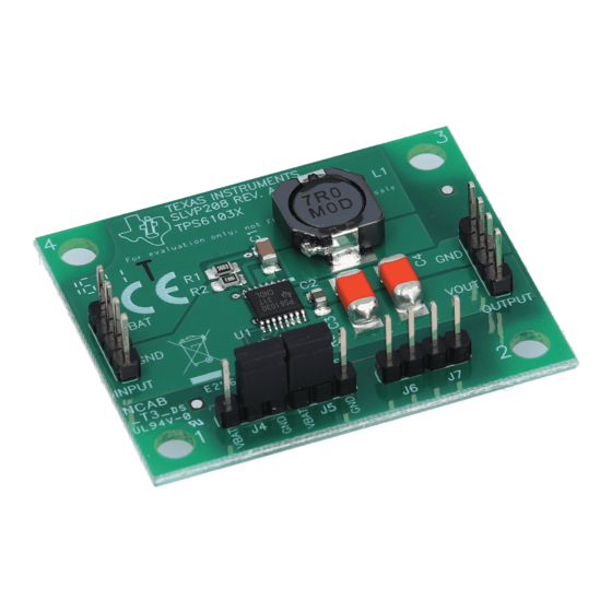
(19 mm × 26 mm) on a double-sided PCB, as it is indicated by the Figure 1 component placement. SLVU080B – January 2003 – Revised September 2016 TPS6103x EVM-208 For High Efficient Output Current Boost Converter Submit Documentation Feedback Copyright © 2003–2016, Texas Instruments Incorporated... -
Page 4: Component Placement
Bill of Materials, PCB Layout, and Schematic www.ti.com Figure 1. Component Placement Figure 2. PCB Top Layer TPS6103x EVM-208 For High Efficient Output Current Boost Converter SLVU080B – January 2003 – Revised September 2016 Submit Documentation Feedback Copyright © 2003–2016, Texas Instruments Incorporated... -
Page 5: Pcb Bottom Layer
Bill of Materials, PCB Layout, and Schematic www.ti.com Figure 3. PCB Bottom Layer Schematic Figure 4. TPS6103x EVM Circuit Diagram SLVU080B – January 2003 – Revised September 2016 TPS6103x EVM-208 For High Efficient Output Current Boost Converter Submit Documentation Feedback Copyright © 2003–2016, Texas Instruments Incorporated... - Page 6 Changes from A Revision (October 2007) to B Revision ....................Page ............. • Deleted 1000 mA maximum output current statement in Introduction. Revision History SLVU080B – January 2003 – Revised September 2016 Submit Documentation Feedback Copyright © 2003–2016, Texas Instruments Incorporated...
- Page 7 STANDARD TERMS AND CONDITIONS FOR EVALUATION MODULES Delivery: TI delivers TI evaluation boards, kits, or modules, including any accompanying demonstration software, components, or documentation (collectively, an “EVM” or “EVMs”) to the User (“User”) in accordance with the terms and conditions set forth herein. Acceptance of the EVM is expressly subject to the following terms and conditions.
- Page 8 FCC Interference Statement for Class B EVM devices NOTE: This equipment has been tested and found to comply with the limits for a Class B digital device, pursuant to part 15 of the FCC Rules. These limits are designed to provide reasonable protection against harmful interference in a residential installation.
- Page 9 【無線電波を送信する製品の開発キットをお使いになる際の注意事項】 開発キットの中には技術基準適合証明を受けて いないものがあります。 技術適合証明を受けていないもののご使用に際しては、電波法遵守のため、以下のいずれかの 措置を取っていただく必要がありますのでご注意ください。 1. 電波法施行規則第6条第1項第1号に基づく平成18年3月28日総務省告示第173号で定められた電波暗室等の試験設備でご使用 いただく。 2. 実験局の免許を取得後ご使用いただく。 3. 技術基準適合証明を取得後ご使用いただく。 なお、本製品は、上記の「ご使用にあたっての注意」を譲渡先、移転先に通知しない限り、譲渡、移転できないものとします。 上記を遵守頂けない場合は、電波法の罰則が適用される可能性があることをご留意ください。 日本テキサス・イ ンスツルメンツ株式会社 東京都新宿区西新宿6丁目24番1号 西新宿三井ビル 3.3.3 Notice for EVMs for Power Line Communication: Please see http://www.tij.co.jp/lsds/ti_ja/general/eStore/notice_02.page 電力線搬送波通信についての開発キットをお使いになる際の注意事項については、次のところをご覧くださ い。http://www.tij.co.jp/lsds/ti_ja/general/eStore/notice_02.page SPACER EVM Use Restrictions and Warnings: 4.1 EVMS ARE NOT FOR USE IN FUNCTIONAL SAFETY AND/OR SAFETY CRITICAL EVALUATIONS, INCLUDING BUT NOT LIMITED TO EVALUATIONS OF LIFE SUPPORT APPLICATIONS.
- Page 10 Notwithstanding the foregoing, any judgment may be enforced in any United States or foreign court, and TI may seek injunctive relief in any United States or foreign court. Mailing Address: Texas Instruments, Post Office Box 655303, Dallas, Texas 75265 Copyright © 2015, Texas Instruments Incorporated...
- Page 11 IMPORTANT NOTICE Texas Instruments Incorporated and its subsidiaries (TI) reserve the right to make corrections, enhancements, improvements and other changes to its semiconductor products and services per JESD46, latest issue, and to discontinue any product or service per JESD48, latest issue.
Need help?
Do you have a question about the TPS6103 Series and is the answer not in the manual?
Questions and answers