Table of Contents
Advertisement
Quick Links
TPS543C20EVM-054 40-A Single Phase Synchronous
This user's guide describes the characteristics, operation, and use of the TPS543C20EVM-054 evaluation
module (EVM). The user's guide includes test information, descriptions, and results. A complete schematic
diagram, printed-circuit board layouts, and bill of materials are also included in this document. Throughout
this user's guide, the abbreviations EVM, TPS543C20EVM-054, and the term evaluation module are
synonymous with the TPS543C20EVM-054, unless otherwise noted.
...................................................................................................................
1
1.1
....................................................................................................................
2
2.1
2.2
3
.....................................................................................................................
4
5
6
7
8
8.1
8.2
8.3
9
9.1
9.2
9.3
9.4
9.5
9.6
9.7
9.8
10
11
1
2
3
4
5
6
7
..........................................................................................................................
8
Output Ripple and SW Node of 0.9-V Output at 12-V
9
Output Ripple and SW Node of 0.9-V Output at 12-V
SLUUBW8 - July 2018
Submit Documentation Feedback
...................................................................................................
....................................................................................
.......................................................................................................
..............................................................................................................
.................................................................................................................
.................................................................................
...............................................................................................................
.............................................................................................................
.............................................................................................
...........................................................................................................
.........................................................................................................
...................................................................................................
...............................................................................................
......................................................................................................
..........................................................................................................
................................................................................................
.....................................................................................................
.............................................................................................................
....................................................................................................
.....................................................................................................
...............................................................................................
.......................................................................................
....................................................................................
.........................................................................................
TPS543C20EVM-054 40-A Single Phase Synchronous Step-Down Converter
Copyright © 2018, Texas Instruments Incorporated
Step-Down Converter
Contents
..............................................................................
...........................................................
.................................................................
..............................................................................
List of Figures
, Transient is 15 A to 25 A to 15 A, the Step is 10 A at 40
IN
...............................................
................................................
User's Guide
SLUUBW8 - July 2018
3
3
4
4
4
4
5
6
7
8
9
9
9
10
10
10
10
11
11
12
13
14
15
16
26
5
7
7
10
10
11
11
12
12
1
Advertisement
Table of Contents

Subscribe to Our Youtube Channel
Related Manuals for Texas Instruments TPS543C20EVM-054


Summary of Contents for Texas Instruments TPS543C20EVM-054
-
Page 1: Table Of Contents
TPS543C20EVM-054 40-A Single Phase Synchronous Step-Down Converter This user's guide describes the characteristics, operation, and use of the TPS543C20EVM-054 evaluation module (EVM). The user's guide includes test information, descriptions, and results. A complete schematic diagram, printed-circuit board layouts, and bill of materials are also included in this document. Throughout this user's guide, the abbreviations EVM, TPS543C20EVM-054, and the term evaluation module are synonymous with the TPS543C20EVM-054, unless otherwise noted. -
Page 2: Sluubw8 – July
List of Test Points for Efficiency Measurements .................... BSR054EVM List of Materials Trademarks All trademarks are the property of their respective owners. TPS543C20EVM-054 40-A Single Phase Synchronous Step-Down Converter SLUUBW8 – July 2018 Submit Documentation Feedback Copyright © 2018, Texas Instruments Incorporated... -
Page 3: Introduction
Introduction www.ti.com Introduction The BSR054EVM evaluation module uses the TPS543C20EVM-054 device. The TPS543C20EVM-054 is a highly integrated synchronous buck converter that is designed for up to 40-A current output. Before You Begin The following warnings and cautions are noted for the safety of anyone using or working close to the TPS543C20EVM-054. -
Page 4: Description
The BSR054EVM is designed as a single output DC/DC converter that demonstrates the TPS543C20EVM-054 in a typical low-voltage application while providing a number of test points to evaluate the performance. It uses a nominal 12-V input bus to produce a regulated 0.9-V output at up to 40-A load current. -
Page 5: Schematic
Schematic www.ti.com Schematic Figure 1. BSR054EVM Schematic SLUUBW8 – July 2018 TPS543C20EVM-054 40-A Single Phase Synchronous Step-Down Converter Submit Documentation Feedback Copyright © 2018, Texas Instruments Incorporated... -
Page 6: Test Equipment
VOUT positive and 2 wires parallel for the VOUT negative) of no more than 1.98 feet between the EVM and the load. This recommended wire gauge and length should achieve a voltage drop of no more than 0.2 V at the maximum 40-A load. TPS543C20EVM-054 40-A Single Phase Synchronous Step-Down Converter SLUUBW8 – July 2018 Submit Documentation Feedback... -
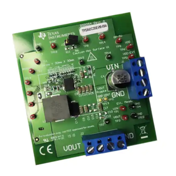
Page 7: Bsr054Evm
BSR054EVM www.ti.com BSR054EVM Figure 2. BSR054EVM Overview Spacer Metal Ground Barrel Probe Figure 3. Tip and Barrel Measurement SLUUBW8 – July 2018 TPS543C20EVM-054 40-A Single Phase Synchronous Step-Down Converter Submit Documentation Feedback Copyright © 2018, Texas Instruments Incorporated... -
Page 8: List Of Test Points, Jumpers, And Switch
Not used TP21, TP22 TP18 T-H loop SYNC Synchronize with external switching frequency 2-pin jumper Enable or disable TPS543C20EVM-054 IC TPS543C20EVM-054 40-A Single Phase Synchronous Step-Down Converter SLUUBW8 – July 2018 Submit Documentation Feedback Copyright © 2018, Texas Instruments Incorporated... -
Page 9: Test Procedure
Using these measurement points result in efficiency measurements that do not include losses due to the connectors and PCB traces. SLUUBW8 – July 2018 TPS543C20EVM-054 40-A Single Phase Synchronous Step-Down Converter Submit Documentation Feedback Copyright © 2018, Texas Instruments Incorporated... -
Page 10: Equipment Shutdown
, 0.9 V , 500 kHz, 25 qC Iout (A) D003 Figure 5. Power Loss of 0.9-V Output vs Load TPS543C20EVM-054 40-A Single Phase Synchronous Step-Down Converter SLUUBW8 – July 2018 Submit Documentation Feedback Copyright © 2018, Texas Instruments Incorporated... -
Page 11: Load Regulation
Figure 7. Transient Response of 0.9-V Output at 12-V , Transient is 15 A to 25 A to 15 A, the Step is 10 A at 40 A/µs SLUUBW8 – July 2018 TPS543C20EVM-054 40-A Single Phase Synchronous Step-Down Converter Submit Documentation Feedback Copyright © 2018, Texas Instruments Incorporated... -
Page 12: Output Ripple
Figure 8. Output Ripple and SW Node of 0.9-V Output at 12-V , 40-A Output Figure 9. Output Ripple and SW Node of 0.9-V Output at 12-V , 0-A Output TPS543C20EVM-054 40-A Single Phase Synchronous Step-Down Converter SLUUBW8 – July 2018 Submit Documentation Feedback Copyright © 2018, Texas Instruments Incorporated... -
Page 13: Control On
Figure 10. Start up from Control, 0.9-V Output at 12-V , 10-mA Output Figure 11. 0.5-V Pre-bias start up from Control, 0.9-V Output at 12-V , 20-A Output SLUUBW8 – July 2018 TPS543C20EVM-054 40-A Single Phase Synchronous Step-Down Converter Submit Documentation Feedback Copyright © 2018, Texas Instruments Incorporated... -
Page 14: Control On And Off
Performance Data and Typical Characteristic Curves www.ti.com Control On and Off Figure 12. Output Voltage Start-up and Shutdown, 0.9-V Output at 12-V , 0.5-A Output TPS543C20EVM-054 40-A Single Phase Synchronous Step-Down Converter SLUUBW8 – July 2018 Submit Documentation Feedback Copyright © 2018, Texas Instruments Incorporated... -
Page 15: Thermal Image
Performance Data and Typical Characteristic Curves www.ti.com Thermal Image Figure 13. Thermal Image at 0.9-V Output at 12 V , 40-A Output, at 25°C Ambient SLUUBW8 – July 2018 TPS543C20EVM-054 40-A Single Phase Synchronous Step-Down Converter Submit Documentation Feedback Copyright © 2018, Texas Instruments Incorporated... -
Page 16: Evm Assembly Drawing And Pcb Layout
BSR054EVM has a 2-oz. copper finish for all layers. Spacer Figure 14. BSR054EVM Top Layer Assembly Drawing (Top View) spacer TPS543C20EVM-054 40-A Single Phase Synchronous Step-Down Converter SLUUBW8 – July 2018 Submit Documentation Feedback Copyright © 2018, Texas Instruments Incorporated... - Page 17 EVM Assembly Drawing and PCB Layout www.ti.com Figure 15. BSR054EVM Top Solder Mask (Top View) SLUUBW8 – July 2018 TPS543C20EVM-054 40-A Single Phase Synchronous Step-Down Converter Submit Documentation Feedback Copyright © 2018, Texas Instruments Incorporated...
- Page 18 EVM Assembly Drawing and PCB Layout www.ti.com Figure 16. BSR054EVM Top Layer (Top View) spacer TPS543C20EVM-054 40-A Single Phase Synchronous Step-Down Converter SLUUBW8 – July 2018 Submit Documentation Feedback Copyright © 2018, Texas Instruments Incorporated...
- Page 19 EVM Assembly Drawing and PCB Layout www.ti.com Figure 17. BSR054EVM Inner Layer 1 (Top View) SLUUBW8 – July 2018 TPS543C20EVM-054 40-A Single Phase Synchronous Step-Down Converter Submit Documentation Feedback Copyright © 2018, Texas Instruments Incorporated...
- Page 20 EVM Assembly Drawing and PCB Layout www.ti.com Figure 18. BSR054EVM Inner Layer 2 (Top View) spacer TPS543C20EVM-054 40-A Single Phase Synchronous Step-Down Converter SLUUBW8 – July 2018 Submit Documentation Feedback Copyright © 2018, Texas Instruments Incorporated...
- Page 21 EVM Assembly Drawing and PCB Layout www.ti.com Figure 19. BSR054EVM Inner Layer 3 (Top View) SLUUBW8 – July 2018 TPS543C20EVM-054 40-A Single Phase Synchronous Step-Down Converter Submit Documentation Feedback Copyright © 2018, Texas Instruments Incorporated...
- Page 22 EVM Assembly Drawing and PCB Layout www.ti.com Figure 20. BSR054EVM Inner Layer 4 (Top View) spacer TPS543C20EVM-054 40-A Single Phase Synchronous Step-Down Converter SLUUBW8 – July 2018 Submit Documentation Feedback Copyright © 2018, Texas Instruments Incorporated...
- Page 23 EVM Assembly Drawing and PCB Layout www.ti.com Figure 21. BSR054EVM Bottom Layer (Top View) SLUUBW8 – July 2018 TPS543C20EVM-054 40-A Single Phase Synchronous Step-Down Converter Submit Documentation Feedback Copyright © 2018, Texas Instruments Incorporated...
- Page 24 EVM Assembly Drawing and PCB Layout www.ti.com Figure 22. BSR054EVM Bottom Solder Mask (Top View) spacer TPS543C20EVM-054 40-A Single Phase Synchronous Step-Down Converter SLUUBW8 – July 2018 Submit Documentation Feedback Copyright © 2018, Texas Instruments Incorporated...
- Page 25 EVM Assembly Drawing and PCB Layout www.ti.com Figure 23. BSR054EVM Bottom Overlay Layer (Top View) SLUUBW8 – July 2018 TPS543C20EVM-054 40-A Single Phase Synchronous Step-Down Converter Submit Documentation Feedback Copyright © 2018, Texas Instruments Incorporated...
-
Page 26: List Of Materials
RC0805JR-073RL Yageo America Unless otherwise noted in the Alternate PartNumber and/or Alternate Manufacturer columns, all parts may be substituted with equivalents. TPS543C20EVM-054 40-A Single Phase Synchronous Step-Down Converter SLUUBW8 – July 2018 Submit Documentation Feedback Copyright © 2018, Texas Instruments Incorporated... - Page 27 RES, 0, 5%, 0.1 W, 0603 0603 CRCW06030000Z0EA Vishay-Dale 8.66k RES, 8.66 k, 1%, 0.063 W, 0402 0402 CRCW04028K66FKED Vishay-Dale SLUUBW8 – July 2018 TPS543C20EVM-054 40-A Single Phase Synchronous Step-Down Converter Submit Documentation Feedback Copyright © 2018, Texas Instruments Incorporated...
- Page 28 STANDARD TERMS FOR EVALUATION MODULES Delivery: TI delivers TI evaluation boards, kits, or modules, including any accompanying demonstration software, components, and/or documentation which may be provided together or separately (collectively, an “EVM” or “EVMs”) to the User (“User”) in accordance with the terms set forth herein.
- Page 29 FCC Interference Statement for Class B EVM devices NOTE: This equipment has been tested and found to comply with the limits for a Class B digital device, pursuant to part 15 of the FCC Rules. These limits are designed to provide reasonable protection against harmful interference in a residential installation.
- Page 30 【無線電波を送信する製品の開発キットをお使いになる際の注意事項】 開発キットの中には技術基準適合証明を受けて いないものがあります。 技術適合証明を受けていないもののご使用に際しては、電波法遵守のため、以下のいずれかの 措置を取っていただく必要がありますのでご注意ください。 1. 電波法施行規則第6条第1項第1号に基づく平成18年3月28日総務省告示第173号で定められた電波暗室等の試験設備でご使用 いただく。 2. 実験局の免許を取得後ご使用いただく。 3. 技術基準適合証明を取得後ご使用いただく。 なお、本製品は、上記の「ご使用にあたっての注意」を譲渡先、移転先に通知しない限り、譲渡、移転できないものとします。 上記を遵守頂けない場合は、電波法の罰則が適用される可能性があることをご留意ください。 日本テキサス・イ ンスツルメンツ株式会社 東京都新宿区西新宿6丁目24番1号 西新宿三井ビル 3.3.3 Notice for EVMs for Power Line Communication: Please see http://www.tij.co.jp/lsds/ti_ja/general/eStore/notice_02.page 電力線搬送波通信についての開発キットをお使いになる際の注意事項については、次のところをご覧ください。http:/ /www.tij.co.jp/lsds/ti_ja/general/eStore/notice_02.page 3.4 European Union 3.4.1 For EVMs subject to EU Directive 2014/30/EU (Electromagnetic Compatibility Directive): This is a class A product intended for use in environments other than domestic environments that are connected to a low-voltage power-supply network that supplies buildings used for domestic purposes.
- Page 31 Notwithstanding the foregoing, any judgment may be enforced in any United States or foreign court, and TI may seek injunctive relief in any United States or foreign court. Mailing Address: Texas Instruments, Post Office Box 655303, Dallas, Texas 75265 Copyright © 2018, Texas Instruments Incorporated...
- Page 32 IMPORTANT NOTICE FOR TI DESIGN INFORMATION AND RESOURCES Texas Instruments Incorporated (‘TI”) technical, application or other design advice, services or information, including, but not limited to, reference designs and materials relating to evaluation modules, (collectively, “TI Resources”) are intended to assist designers who are developing applications that incorporate TI products;...
Need help?
Do you have a question about the TPS543C20EVM-054 and is the answer not in the manual?
Questions and answers