Table of Contents
Advertisement
Quick Links
The TPS62840-1YBGEVM56 (BSR056-001) facilitates the evaluation of the TPS6284xYBG family of 750-
mA, step-down converters with 60-nA I
The EVM contains 2 separate circuits to create output voltages between 0.8 V and 3.3 V from higher input
voltages between 1.8 V and 6.5 V. All circuits have a maximum height of 1 mm. Due to its extremely low
I
, the TPS6284x provides a long battery lifetime for systems which have very low current consumption
Q
states such as wearables, Internet of Things- (IoT-) connected devices, and other portable end equipment.
...................................................................................................................
1
..........................................................................................................................
2
3
4
5
1
2
TPS62840 Thermal Performance (V
3
4
.....................................................................................................................
5
6
7
8
9
10
11
12
1
BSR056 Circuit Options
2
Performance Specification Summary
3
4
Trademarks
All trademarks are the property of their respective owners.
SLUUC17 - May 2019
Submit Documentation Feedback
TPS62840-1YBGEVM56 User's Guide
in tiny 1.47-mm by 0.97-mm WCSP packages with 0.4-mm pitch.
Q
....................................................................................
.................................................................................................................
..................................................................................
= 3.6 V, V
IN
= 3.6 V, V
= 1.8 V, I
IN
OUT
................................................................................................................
..............................................................................................................
..............................................................................................................
................................................................................................................
..................................................................................
...............................................................................
......................................................................................................
......................................................................................................
.....................................................................................................
.....................................................................................
................................................................................................
................................................................................................
Copyright © 2019, Texas Instruments Incorporated
Contents
List of Figures
..............................................................................
= 1.8 V, I
= 750 mA)
OUT
OUT
.............................................................
= 750 mA)
OUT
List of Tables
TPS62840-1YBGEVM56 User's Guide
User's Guide
SLUUC17 - May 2019
........................................
2
4
5
6
12
3
5
5
6
7
8
9
10
11
11
12
12
2
2
13
13
1
Advertisement
Table of Contents

Subscribe to Our Youtube Channel
Related Manuals for Texas Instruments TPS62840-1YBGEVM56


Summary of Contents for Texas Instruments TPS62840-1YBGEVM56
-
Page 1: Table Of Contents
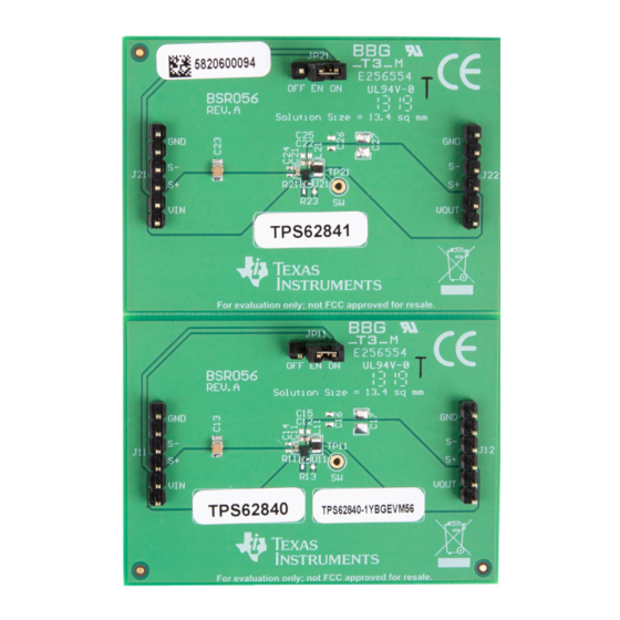
User's Guide SLUUC17 – May 2019 TPS62840-1YBGEVM56 User's Guide The TPS62840-1YBGEVM56 (BSR056-001) facilitates the evaluation of the TPS6284xYBG family of 750- mA, step-down converters with 60-nA I in tiny 1.47-mm by 0.97-mm WCSP packages with 0.4-mm pitch. The EVM contains 2 separate circuits to create output voltages between 0.8 V and 3.3 V from higher input voltages between 1.8 V and 6.5 V. - Page 2 TPS62840-1YBGEVM56 (BSR056-001) TPS62841 (U21) 1.2 V 0.8 - 1.55 V (selectable) 750 mA Performance Specification Table 2 provides a summary of the TPS62840-1YBGEVM56 performance specifications. Table 2. Performance Specification Summary SPECIFICATION UNIT Input voltage Output voltage Table 1 Output current...
-
Page 3: Introduction
How to Measure the Control Loop of DCS-Control™ Devices. The results of this test are shown in Figure Cut trace as shown Figure 1. Loop Response Measurement Modification SLUUC17 – May 2019 TPS62840-1YBGEVM56 User's Guide Submit Documentation Feedback Copyright © 2019, Texas Instruments Incorporated... -
Page 4: Setup
Setup www.ti.com Setup This section describes how to properly use the TPS62840-1YBGEVM56. Input/Output Connector Descriptions Jx1, Pin 1 and 2 – VIN Positive input connection from the input supply for the EVM. Jx1, Pin 3 and 4 – S+/S- Input voltage sense connections. Measure the input voltage at this point. -
Page 5: Tps62840-1Ybgevm56 Test Results
TPS62840-1YBGEVM56 Test Results www.ti.com TPS62840-1YBGEVM56 Test Results The TPS62840-1YBGEVM56 was used to take all the data in the 1.8V-6.5V, 750mA, 60nA I Step-Down Converter data sheet. See the device data sheet for the performance of this EVM. The only difference is the inductor used. -
Page 6: Board Layout
Board Layout This section provides the TPS62840-1YBGEVM56 board layout and illustrations in Figure 4 through Figure 8. The Gerbers are available on the EVM product page: TPS62840-1YBGEVM56. Figure 4. Top Assembly TPS62840-1YBGEVM56 User's Guide SLUUC17 – May 2019 Submit Documentation Feedback... -
Page 7: Top Layer
Board Layout www.ti.com Figure 5. Top Layer SLUUC17 – May 2019 TPS62840-1YBGEVM56 User's Guide Submit Documentation Feedback Copyright © 2019, Texas Instruments Incorporated... -
Page 8: Internal Layer
Board Layout www.ti.com Figure 6. Internal Layer 1 TPS62840-1YBGEVM56 User's Guide SLUUC17 – May 2019 Submit Documentation Feedback Copyright © 2019, Texas Instruments Incorporated... -
Page 9: Internal Layer
Board Layout www.ti.com Figure 7. Internal Layer 2 SLUUC17 – May 2019 TPS62840-1YBGEVM56 User's Guide Submit Documentation Feedback Copyright © 2019, Texas Instruments Incorporated... -
Page 10: Bottom Layer
Board Layout www.ti.com Figure 8. Bottom Layer TPS62840-1YBGEVM56 User's Guide SLUUC17 – May 2019 Submit Documentation Feedback Copyright © 2019, Texas Instruments Incorporated... -
Page 11: Tps62840-1Ybgevm56 Angled View
Board Layout www.ti.com Figure 9. TPS62840-1YBGEVM56 Angled View Figure 10. TPS62840-1YBGEVM56 Overhead View SLUUC17 – May 2019 TPS62840-1YBGEVM56 User's Guide Submit Documentation Feedback Copyright © 2019, Texas Instruments Incorporated... -
Page 12: Schematic And Bill Of Materials (Bom)
Schematic and Bill of Materials (BOM) www.ti.com Schematic and Bill of Materials (BOM) This section provides the TPS62840-1YBGEVM56 schematic and bill of materials. Schematic Figure 11 illustrates the TPS62840 EVM schematic. Figure 11. TPS62840 Schematic Figure 12 illustrates the TPS62841 EVM schematic. -
Page 13: Tps62840 Bill Of Materials
DFE201210S-2R2M=P2 Murata RES, 15.8 kΩ, 1%, 0.05 W, 0201 1.8V to 6.5V, 750mA, 60nA I Step Down Converter in WCSP TPS62841YBG Texas Instruments Package SLUUC17 – May 2019 TPS62840-1YBGEVM56 User's Guide Submit Documentation Feedback Copyright © 2019, Texas Instruments Incorporated... - Page 14 STANDARD TERMS FOR EVALUATION MODULES Delivery: TI delivers TI evaluation boards, kits, or modules, including any accompanying demonstration software, components, and/or documentation which may be provided together or separately (collectively, an “EVM” or “EVMs”) to the User (“User”) in accordance with the terms set forth herein.
- Page 15 www.ti.com Regulatory Notices: 3.1 United States 3.1.1 Notice applicable to EVMs not FCC-Approved: FCC NOTICE: This kit is designed to allow product developers to evaluate electronic components, circuitry, or software associated with the kit to determine whether to incorporate such items in a finished product and software developers to write software applications for use with the end product.
- Page 16 www.ti.com Concernant les EVMs avec antennes détachables Conformément à la réglementation d'Industrie Canada, le présent émetteur radio peut fonctionner avec une antenne d'un type et d'un gain maximal (ou inférieur) approuvé pour l'émetteur par Industrie Canada. Dans le but de réduire les risques de brouillage radioélectrique à...
- Page 17 www.ti.com EVM Use Restrictions and Warnings: 4.1 EVMS ARE NOT FOR USE IN FUNCTIONAL SAFETY AND/OR SAFETY CRITICAL EVALUATIONS, INCLUDING BUT NOT LIMITED TO EVALUATIONS OF LIFE SUPPORT APPLICATIONS. 4.2 User must read and apply the user guide and other available documentation provided by TI regarding the EVM prior to handling or using the EVM, including without limitation any warning or restriction notices.
- Page 18 Notwithstanding the foregoing, any judgment may be enforced in any United States or foreign court, and TI may seek injunctive relief in any United States or foreign court. Mailing Address: Texas Instruments, Post Office Box 655303, Dallas, Texas 75265 Copyright © 2019, Texas Instruments Incorporated...
- Page 19 TI products. TI’s provision of these resources does not expand or otherwise alter TI’s applicable warranties or warranty disclaimers for TI products. Mailing Address: Texas Instruments, Post Office Box 655303, Dallas, Texas 75265 Copyright © 2019, Texas Instruments Incorporated...
Need help?
Do you have a question about the TPS62840-1YBGEVM56 and is the answer not in the manual?
Questions and answers