Table of Contents
Advertisement
Quick Links
Advertisement
Table of Contents

Related Manuals for Texas Instruments TPS53317AEVM-726


Summary of Contents for Texas Instruments TPS53317AEVM-726
- Page 1 Using the TPS53317AEVM-726 User's Guide Literature Number: SLUUBD2 November 2015...
-
Page 2: Table Of Contents
Enable Turn On / Turn Off ....................... Pre-Bias Turn-On ........................ Bode Plot ......................Thermal Image ................EVM Assembly Drawing and PCB Layout ......................... List of Materials Table of Contents SLUUBD2 – November 2015 Submit Documentation Feedback Copyright © 2015, Texas Instruments Incorporated... - Page 3 Thermal Image (1.2-V V , 0.6-V V , 6-A I , PWM Mode, f = 600 kHz) ............ TPS53317AEVM-726 Top Layer Assembly Drawing (Top View) ............ TPS53317AEVM-726 Bottom Assembly Drawing (Bottom View) ................. TPS53317AEVM-726 Top Copper (Top View) ................TPS53317AEVM-726 Layer 2 (Top View) ................
- Page 4 MODE Selection ......................Droop Configuration ..................External Tracking Configuration ......................Enable Selection ..................The Functions of Each Test Points .................. TPS53317AEVM-726 List of Materials List of Tables SLUUBD2 – November 2015 Submit Documentation Feedback Copyright © 2015, Texas Instruments Incorporated...
-
Page 5: Introduction
Description The TPS53317AEVM-726 is designed to use a 1.2-V voltage rail to produce a regulated 0.6-V output at up to 6-A load current. The TPS53317AEVM-726 is designed to demonstrate the TPS53317A in a typical low voltage application while providing a number of test points to evaluate the performance of the TPS53317A. -
Page 6: Electrical Performance Specifications
Electrical Performance Specifications www.ti.com Electrical Performance Specifications Table 1 contains the TPS53317AEVM-726 electrical performance specifications. Table 1. TPS53317AEVM-726 Electrical Performance Specifications Parameter Test Conditions Units Input Characteristics Voltage range Maximum input current = 1.2 V, I = 6 A No load input current = 1.2 V, I... -
Page 7: Schematic
22µF 22µF TP14 3.92k 23.2k TP11 TP15 AGND REFIN 10.0k 10.0k 0.01µF TP10 AGND AGND Figure 1. TPS53317AEVM-726 Schematic SLUUBD2 – November 2015 TPS53317AEVM-726 D-CAP+™ Mode Synchronous Step-Down Integrated FETs Converter Submit Documentation Feedback Copyright © 2015, Texas Instruments Incorporated... -
Page 8: Test Setup
V5IN to J3 (5-V input): The recommended wire size is 1x AWG #16 per input connection, with the total length of wire less than 4 feet (2-feet input, 2-feet return). TPS53317AEVM-726 D-CAP+™ Mode Synchronous Step-Down Integrated SLUUBD2 – November 2015... -
Page 9: Recommended Test Setup
Recommended Test Setup Figure 3 is the recommended test set up to evaluate the TPS53317AEVM-726. Working at an ESD workstation, make sure that any wrist straps, bootstraps or mats are connected referencing the user to earth ground before power is applied to the EVM. -
Page 10: Configurations
Default Setting: Non-Droop Table 3. Droop Configuration Jumper Setting Droop Configuration Top(1-2 pin shorted) Droop Bottom(2-3 pin shorted) Non-droop TPS53317AEVM-726 D-CAP+™ Mode Synchronous Step-Down Integrated SLUUBD2 – November 2015 FETs Converter Submit Documentation Feedback Copyright © 2015, Texas Instruments Incorporated... -
Page 11: External Tracking Selection
10. Set switch S1 to DIS to disable the controller. 11. Decrease Load to 0 A. 12. Decrease VIN to 0 V. 13. Decrease V5IN to 0 V. SLUUBD2 – November 2015 TPS53317AEVM-726 D-CAP+™ Mode Synchronous Step-Down Integrated FETs Converter Submit Documentation Feedback Copyright © 2015, Texas Instruments Incorporated... -
Page 12: Control Loop Gain And Phase Measurement Procedure
Test Procedure www.ti.com Control Loop Gain and Phase Measurement Procedure TPS53317AEVM-726 contains a 10-Ω series resistor in the feedback loop for loop response analysis. 1. Set up EVM as described in Figure 2. Connect isolation transformer to test points marked TP12 and TP13. -
Page 13: Performance Data And Typical Characteristic Curves
Performance Data and Typical Characteristic Curves www.ti.com Performance Data and Typical Characteristic Curves Figure 4 through Figure 15 present typical performance curves for TPS53317AEVM-726. Efficiency PWM Mode, 600 kHz PWM Mode, 1 MHz D002 Figure 4. Efficiency Load Regulation 0.61 0.605... -
Page 14: Output Transient
Figure 7. Output Load 0-A to 3-A Transient with Droop (1.2-V V , 0.6-V V , PWM Mode, f = 600 kHz) TPS53317AEVM-726 D-CAP+™ Mode Synchronous Step-Down Integrated SLUUBD2 – November 2015 FETs Converter Submit Documentation Feedback Copyright © 2015, Texas Instruments Incorporated... -
Page 15: Output Ripple
, 3-A I = 600 kHz) Figure 9. Output Ripple (1.2-V V , 0.6-V V , 3-A I = 1 MHz) SLUUBD2 – November 2015 TPS53317AEVM-726 D-CAP+™ Mode Synchronous Step-Down Integrated FETs Converter Submit Documentation Feedback Copyright © 2015, Texas Instruments Incorporated... -
Page 16: Switching Node
, 3-A I = 600 kHz) Figure 11. Switching Node (1.2-V V , 0.6-V V , 3-A I = 1 MHz) TPS53317AEVM-726 D-CAP+™ Mode Synchronous Step-Down Integrated SLUUBD2 – November 2015 FETs Converter Submit Documentation Feedback Copyright © 2015, Texas Instruments Incorporated... -
Page 17: Enable Turn On / Turn Off
(1.2-V V , 0.6-V V , 3-A I Figure 13. Turn-Off Waveform (1.2-V V , 0.6-V V , 3-A I SLUUBD2 – November 2015 TPS53317AEVM-726 D-CAP+™ Mode Synchronous Step-Down Integrated FETs Converter Submit Documentation Feedback Copyright © 2015, Texas Instruments Incorporated... -
Page 18: Pre-Bias Turn-On
Figure 15. Loop Gain (1.2-V V , 0.6-V V , 3-A I , PWM Mode, f = 600 kHz, Non-Droop) TPS53317AEVM-726 D-CAP+™ Mode Synchronous Step-Down Integrated SLUUBD2 – November 2015 FETs Converter Submit Documentation Feedback Copyright © 2015, Texas Instruments Incorporated... -
Page 19: Thermal Image
Figure 16. Thermal Image (1.2-V V , 0.6-V V , 6-A I , PWM Mode, f = 600 kHz) SLUUBD2 – November 2015 TPS53317AEVM-726 D-CAP+™ Mode Synchronous Step-Down Integrated FETs Converter Submit Documentation Feedback Copyright © 2015, Texas Instruments Incorporated... -
Page 20: Evm Assembly Drawing And Pcb Layout
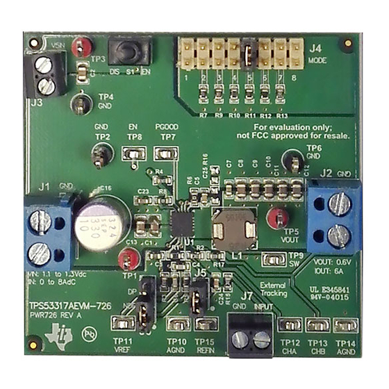
22) show the design of the TPS53317AEVM-726 printed circuit board. The EVM has been designed using 4-Layers, 2-oz copper circuit board. Figure 17. TPS53317AEVM-726 Top Layer Assembly Drawing (Top View) Figure 18. TPS53317AEVM-726 Bottom Assembly Drawing (Bottom View) TPS53317AEVM-726 D-CAP+™ Mode Synchronous Step-Down Integrated SLUUBD2 –... -
Page 21: Tps53317Aevm-726 Top Copper (Top View)
EVM Assembly Drawing and PCB Layout www.ti.com Figure 19. TPS53317AEVM-726 Top Copper (Top View) Figure 20. TPS53317AEVM-726 Layer 2 (Top View) SLUUBD2 – November 2015 TPS53317AEVM-726 D-CAP+™ Mode Synchronous Step-Down Integrated FETs Converter Submit Documentation Feedback Copyright © 2015, Texas Instruments Incorporated... -
Page 22: Tps53317Aevm-726 Layer 3 (Top View)
EVM Assembly Drawing and PCB Layout www.ti.com Figure 21. TPS53317AEVM-726 Layer 3 (Top View) Figure 22. TPS53317AEVM-726 Bottom Layer (Top View) TPS53317AEVM-726 D-CAP+™ Mode Synchronous Step-Down Integrated SLUUBD2 – November 2015 FETs Converter Submit Documentation Feedback Copyright © 2015, Texas Instruments Incorporated... -
Page 23: List Of Materials
List of Materials www.ti.com List of Materials The EVM components list according to the schematic shown in Figure Table 7. TPS53317AEVM-726 List of Materials Designator Description Part Number Manufactur C1, C13, C14, CAP, CERM, 10 µF, 16 V, +/- 10%, X5R, 0805 CAP, CERM, 10 µF, 10 V, +/- 10%, X5R, 0805... - Page 24 List of Materials www.ti.com Table 7. TPS53317AEVM-726 List of Materials (continued) Designator Description Part Number Manufactur 6-A Output D-CAP+ Mode Synchronous Step-Down, Integrated-FET Converter TPS53317ARGBR Texas for DDR Memory Termination Instruments TPS53317AEVM-726 D-CAP+™ Mode Synchronous Step-Down Integrated SLUUBD2 – November 2015...
- Page 25 Evaluation Board/Kit Important Notice Texas Instruments (TI) provides the enclosed product(s) under the following conditions: This evaluation board/kit is intended for use for ENGINEERING DEVELOPMENT, DEMONSTRATION, OR EVALUATION PURPOSES ONLY and is not considered by TI to be a finished end-product fit for general consumer use. Persons handling the product(s) must have electronics training and observe good engineering practice standards.
- Page 26 STANDARD TERMS AND CONDITIONS FOR EVALUATION MODULES Delivery: TI delivers TI evaluation boards, kits, or modules, including any accompanying demonstration software, components, or documentation (collectively, an “EVM” or “EVMs”) to the User (“User”) in accordance with the terms and conditions set forth herein. Acceptance of the EVM is expressly subject to the following terms and conditions.
- Page 27 FCC Interference Statement for Class B EVM devices NOTE: This equipment has been tested and found to comply with the limits for a Class B digital device, pursuant to part 15 of the FCC Rules. These limits are designed to provide reasonable protection against harmful interference in a residential installation.
- Page 28 【無線電波を送信する製品の開発キットをお使いになる際の注意事項】 開発キットの中には技術基準適合証明を受けて いないものがあります。 技術適合証明を受けていないもののご使用に際しては、電波法遵守のため、以下のいずれかの 措置を取っていただく必要がありますのでご注意ください。 1. 電波法施行規則第6条第1項第1号に基づく平成18年3月28日総務省告示第173号で定められた電波暗室等の試験設備でご使用 いただく。 2. 実験局の免許を取得後ご使用いただく。 3. 技術基準適合証明を取得後ご使用いただく。 なお、本製品は、上記の「ご使用にあたっての注意」を譲渡先、移転先に通知しない限り、譲渡、移転できないものとします。 上記を遵守頂けない場合は、電波法の罰則が適用される可能性があることをご留意ください。 日本テキサス・イ ンスツルメンツ株式会社 東京都新宿区西新宿6丁目24番1号 西新宿三井ビル 3.3.3 Notice for EVMs for Power Line Communication: Please see http://www.tij.co.jp/lsds/ti_ja/general/eStore/notice_02.page 電力線搬送波通信についての開発キットをお使いになる際の注意事項については、次のところをご覧くださ い。http://www.tij.co.jp/lsds/ti_ja/general/eStore/notice_02.page SPACER EVM Use Restrictions and Warnings: 4.1 EVMS ARE NOT FOR USE IN FUNCTIONAL SAFETY AND/OR SAFETY CRITICAL EVALUATIONS, INCLUDING BUT NOT LIMITED TO EVALUATIONS OF LIFE SUPPORT APPLICATIONS.
- Page 29 Notwithstanding the foregoing, any judgment may be enforced in any United States or foreign court, and TI may seek injunctive relief in any United States or foreign court. Mailing Address: Texas Instruments, Post Office Box 655303, Dallas, Texas 75265 Copyright © 2015, Texas Instruments Incorporated...
- Page 30 IMPORTANT NOTICE Texas Instruments Incorporated and its subsidiaries (TI) reserve the right to make corrections, enhancements, improvements and other changes to its semiconductor products and services per JESD46, latest issue, and to discontinue any product or service per JESD48, latest issue.
Need help?
Do you have a question about the TPS53317AEVM-726 and is the answer not in the manual?
Questions and answers