Advertisement
Quick Links
This document is the user guide for the TPS66020 Evaluation Module (TPS66020EVM). The
TPS66020EVM allows for evaluation of the TPS66020 IC as part of a stand-alone testing kit and testing of
USB Type-C and Power Delivery (PD) end products. Out of the box, the TPS66020EVM can be used to
test the Source and Sink paths in addition to trying the different protection schemes, such as OVP
(Overvoltage Protection).
...................................................................................................................
1
Introduction
2
3
4
5
1
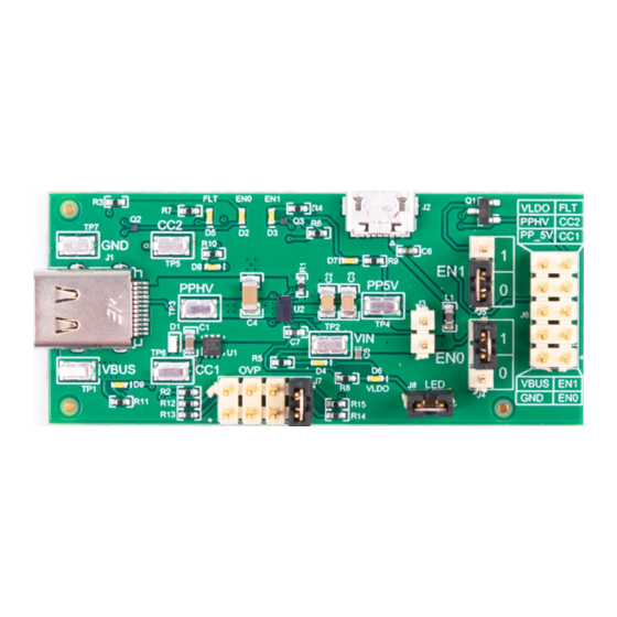
TPS66020EVM Board
2
TPS660020EVM Block Diagram
3
Supplying Power to the TPS66020EVM Using the Micro-USB Connector J2
4
Source Path Configuration
5
Sink Path Configuration
6
Overvoltage Protection Level Jumper
7
Connecting the TPS66020EVM to the PD Controller TPS65988 EVM
8
PD Transactions and VBUS Timing Waveform
9
1
TPS66020 Functional Table and EVM Jumper Settings
2
Jumpers Description
3
Connector Functionality
....................................................................................................................
4
Test Points
5
Trademarks
1
Introduction
Texas Instrument's (TI's) TPS66020 evaluation module helps designers evaluate the operation and
performance of the TPS66020 device.
The TPS66020 is a full-featured power switch multiplexer that contains an integrated 5-V Source power
path and a 4-V to 22-V Sink power path. The 5-V Source path limits the output current to a safe level by
operating in a constant-current mode when the output load exceeds the selected current-limit threshold.
Each power path supports overtemperature and reverse current protection. VBUS has overvoltage
protection with its level being set by an optional external resistor divider. If no overvoltage protection is
desired, it may be disabled by grounding the OVP terminal. The TPS6602x series supports a fault pin that
indicates overcurrent and overtemperature events.
The TPS66020EVM has jumpers, header and test points that will permit to test the Source and Sink
configuration in addition to the protection schemes.
SLVUBQ4 - July 2019
Submit Documentation Feedback
..............................................................................................
..................................................................................................
...........................................................................................
.......................................................................................................
...........................................................................................
.................................................................................................
....................................................................................................
..................................................................................
..............................................................................................
........................................................................................................
.....................................................................................................
.............................................................................................................
Copyright © 2019, Texas Instruments Incorporated
TPS66020 Evaluation Module
Contents
List of Figures
............................................
.......................................................................
List of Tables
..............................................................
User's Guide
SLVUBQ4 - July 2019
...............................
......................................
TPS66020 Evaluation Module
1
3
4
10
12
2
2
5
6
8
10
10
11
12
3
3
4
4
13
1
Advertisement

Related Manuals for Texas Instruments TPS66020EVM


Summary of Contents for Texas Instruments TPS66020EVM
-
Page 1: Table Of Contents
This document is the user guide for the TPS66020 Evaluation Module (TPS66020EVM). The TPS66020EVM allows for evaluation of the TPS66020 IC as part of a stand-alone testing kit and testing of USB Type-C and Power Delivery (PD) end products. Out of the box, the TPS66020EVM can be used to test the Source and Sink paths in addition to trying the different protection schemes, such as OVP (Overvoltage Protection). - Page 2 Introduction www.ti.com Figure 1 shows the TPS66020EVM board and Figure 2 shows a block level diagram. Figure 1. TPS66020EVM Board Figure 2. TPS660020EVM Block Diagram TPS66020 Evaluation Module SLVUBQ4 – July 2019 Submit Documentation Feedback Copyright © 2019, Texas Instruments Incorporated...
- Page 3 USB 2.0 Micro Cable and Power Supply or a 5V/1A Bench Power supply for power on the TPS66020 device. • One Bench Power Supply up to 25 V, Maximum Current 5 Amps. To source or sink power. • Cables for the power supply and the test points in the TPS66020EVM • DMM (Digital Volt Meter) • Oscilloscope •...
-
Page 4: Tps66020Evm Board Setup
TPS66020EVM Board Setup www.ti.com Connector Functionality Table 3 lists TPS66020EVM connector and functionality Table 3. Connector Functionality Designator Description USB Type -C connector. Micro USB connector. Connect to a PC or USB type power supply to provide operating power to TPS66020. Goes to VIN. - Page 5 Using the TPS66020EVM www.ti.com Figure 3. Supplying Power to the TPS66020EVM Using the Micro-USB Connector J2 Setting the EVM for Sourcing Mode. As described in Section 2.1, there are two different types of sourcing modes, 1.5 A and 3 A. The description under this section is applicable to both modes.
- Page 6 In order to open the source switch, disabling the Sourcing Mode, short pins 1 and 2 on J5. VBUS voltage should be close to 0 V. TPS66020 Evaluation Module SLVUBQ4 – July 2019 Submit Documentation Feedback Copyright © 2019, Texas Instruments Incorporated...
- Page 7 Using the TPS66020EVM www.ti.com SLVUBQ4 – July 2019 TPS66020 Evaluation Module Submit Documentation Feedback Copyright © 2019, Texas Instruments Incorporated...
- Page 8 Change the power supply output connected to VBUS on TP1 to 9 V, 15 V, 20 V and measure at TP3 each time. PP_HV should track the changing voltage applied to VBUS. TPS66020 Evaluation Module SLVUBQ4 – July 2019 Submit Documentation Feedback Copyright © 2019, Texas Instruments Incorporated...
- Page 9 You can easily monitor this with an oscilloscope and adjusting the output of the power supply applied to VBUS. Try the other jumper positions on J7 to change the OVP level to 6.1 V, 10.2 V and 16.4 V. SLVUBQ4 – July 2019 TPS66020 Evaluation Module Submit Documentation Feedback Copyright © 2019, Texas Instruments Incorporated...
-
Page 10: Application Example: Interfacing The Tps66020 Evm With A Pd Controller Evm
This example uses the TI TPS65988 EVM to interface the TPS66020 EVM. Before trying the example, remove the jumpers from J4 and J5 on the TPS66020EVM. TPS65988EVM is configured to control the Sink Path with GPIOs connected to EN0 and EN1 in the TPS66020EVM. - Page 11 Application Example: Interfacing the TPS66020 EVM with a PD Controller EVM. www.ti.com Figure 8. PD Transactions and VBUS Timing Waveform VBUS: TPS66020EVM VBUS. Rises from 0 to 5 V when the PD Power Source is connected to TPS65988EVM Port B Type-C plug.
-
Page 12: Schematic And Bill Of Materials
Schematic and Bill of Materials www.ti.com Schematic and Bill of Materials Schematic Figure 9 illustrate the TPS66020 schematics. Figure 9. TPS66020EVM Schematics Space Space Space Space TPS66020 Evaluation Module SLVUBQ4 – July 2019 Submit Documentation Feedback Copyright © 2019, Texas Instruments Incorporated... -
Page 13: Bill Of Materials
0402 CRCW040275K0FKED Vishay-Dale Grade 0, 0402 Unless otherwise noted in the Alternate PartNumber and/or Alternate Manufacturer columns, all parts may be substituted with equivalents. SLVUBQ4 – July 2019 TPS66020 Evaluation Module Submit Documentation Feedback Copyright © 2019, Texas Instruments Incorporated... - Page 14 Multiplexer with VBUS LDO Regulator, YBG0028-TEMP TPS66020YBG Texas Instruments Texas Instruments YBG0028-TEMP (DSBGA-28) FID1, FID2, Fiducial mark. There is nothing to buy or FID3 mount TPS66020 Evaluation Module SLVUBQ4 – July 2019 Submit Documentation Feedback Copyright © 2019, Texas Instruments Incorporated...
- Page 15 STANDARD TERMS FOR EVALUATION MODULES Delivery: TI delivers TI evaluation boards, kits, or modules, including any accompanying demonstration software, components, and/or documentation which may be provided together or separately (collectively, an “EVM” or “EVMs”) to the User (“User”) in accordance with the terms set forth herein.
- Page 16 www.ti.com Regulatory Notices: 3.1 United States 3.1.1 Notice applicable to EVMs not FCC-Approved: FCC NOTICE: This kit is designed to allow product developers to evaluate electronic components, circuitry, or software associated with the kit to determine whether to incorporate such items in a finished product and software developers to write software applications for use with the end product.
- Page 17 www.ti.com Concernant les EVMs avec antennes détachables Conformément à la réglementation d'Industrie Canada, le présent émetteur radio peut fonctionner avec une antenne d'un type et d'un gain maximal (ou inférieur) approuvé pour l'émetteur par Industrie Canada. Dans le but de réduire les risques de brouillage radioélectrique à...
- Page 18 www.ti.com EVM Use Restrictions and Warnings: 4.1 EVMS ARE NOT FOR USE IN FUNCTIONAL SAFETY AND/OR SAFETY CRITICAL EVALUATIONS, INCLUDING BUT NOT LIMITED TO EVALUATIONS OF LIFE SUPPORT APPLICATIONS. 4.2 User must read and apply the user guide and other available documentation provided by TI regarding the EVM prior to handling or using the EVM, including without limitation any warning or restriction notices.
- Page 19 Notwithstanding the foregoing, any judgment may be enforced in any United States or foreign court, and TI may seek injunctive relief in any United States or foreign court. Mailing Address: Texas Instruments, Post Office Box 655303, Dallas, Texas 75265 Copyright © 2019, Texas Instruments Incorporated...
- Page 20 TI products. TI’s provision of these resources does not expand or otherwise alter TI’s applicable warranties or warranty disclaimers for TI products. Mailing Address: Texas Instruments, Post Office Box 655303, Dallas, Texas 75265 Copyright © 2019, Texas Instruments Incorporated...
Need help?
Do you have a question about the TPS66020EVM and is the answer not in the manual?
Questions and answers