
Related Manuals for Safe Fleet RVS systems RVS-M641


Summary of Contents for Safe Fleet RVS systems RVS-M641
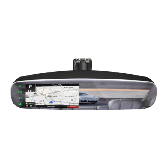
- Page 1 Instruction Manual G-Series Rear View Frameless Mirror Monitor with 4.3" Mirrorlink Display RVS-M641 Reverse With Confidence ™...
-
Page 2: Table Of Contents
Introduction......Safety Information......04-06 Before Beginning Installation . -
Page 3: Introduction
NOTE! Please read all of the installation instructions carefully before installing the product. Improper installation will void manufacturer’s warranty. Congratulations on purchasing a Rear View Backup Camera System! With this manual you will be able to properly install and operate the unit. The Backup Camera System is intended to be installed as a supplement aid to your standard rear view mirror that already exists in your vehicle. -
Page 4: Safety Information
Please read the entire manual and follow the instructions and warnings carefully. Failure to do so can cause serious damage and/or injury, including loss of life. Be sure to obey all applicable local traffic and motor vehicle regulations as it pertains to this product. Improper installation will void manufacturer’s warranty. - Page 5 INSTALLATION: • Electric shock or product or disconnected wire may cause a malfunction may occur if this fire. product is installed incorrectly. • While installing the Rear View System be careful with the wire • Use this product within positioning in order to avoid wire the voltage range specified.
- Page 6 If you have questions about this product, contact: RVS Systems 1797 Atlantic Avenue Brooklyn, NY 11233 Tel: 1.800.764.1028 IN NO EVENT SHALL SELLER OR MANUFACTURER BE LIABLE FOR ANY DIRECT OR CONSEQUENTIAL DAMAGES OF ANY NATURE, OR LOSSES OR EXPENSES RESULTING FROM ANY DEFECTIVE PRODUCT OR THE USE OF ANY PRODUCT.
-
Page 7: Before Beginning Installation
Before drilling please check that no cable or wiring is on the other side of the wall. Please clamp all wires securely to reduce the possibility of them being damaged while vehicle is in use. Keep all cables away from hot/moving parts and electrical noisy components. We recommend doing a benchmark test before installation to insure that all components are working properly. -
Page 8: Installation Guide
Replacement Monitor The mirror monitor replaces the existing car mirror. Carefully remove the mirror off the “pin”. Slide the replacement mirror on to the pin and secure it with the screw provided (already in the screw hole).Differ- ent cars have different brackets. Depending on your vehicle make and manufacturer. - Page 9 Wiring After connecting the camera to the “camera cable” the camera should be plugged into AV2 input. Connect the RED 12V power wire to a an ignition power source and the BLACK 12V ground wire to a chassis ground. The GREEN wire is the REVERSE trigger wire. Connect this wire to the vehicle’s backup light circuit to activate the rear-view image whenever the vehicle shifts into reverse.
-
Page 10: Monitor Introduction
RVS Systems... - Page 11 4.3" Ultra Bright Screen Mirrorlink Mode Switch Toggle Display Mode (Mirrorlink, Camera Displays) Toggle Volume Up Toggle Volume Down Mounting Bracket Connection Input Speaker Black to GND Red to Ignition +12V Reverse Trigger Left Audio Right Audio Camera Input #1 Camera Input #2 Reverse With Confidence ™...
-
Page 12: Adjustable Grid Lines
Grid Lines Generally, to help drivers estimate the distance from obstacles, there are three lines for reference- red, yellow, and green. Those three lines are dis- played on the monitor when car is reversing. The green line is 10 feet from the back of the car and the yellow line is 6.5 feet away. -
Page 13: Installation + Wire
FIGURE 1.1 FIGURE 1.2 Reverse With Confidence ™... - Page 14 FIGURE 2.1 1. RED- Power (+) 2. YELLOW- Video 3. GREEN- Mirror / Normal Imaging 4. WHITE- Audio 5. BLACK- Ground (-) RVS Systems...
- Page 15 FIGURE 2.2 Reverse With Confidence ™...
-
Page 16: Remote Introduction
Remote Introduction Remote Introduction Press the button to toggle L/R gridlines Clockwise Left Right Down Counterclockwise Remote control Adjust grid line Rotate gride line RVS Systems... -
Page 17: Menu Introduction
Menu Introduction Menu Introduction Short press the Menu to toggle between Picture and System. Once in these settings, press Sel/Rec to switch among items. Use Up and Down to adjust settings. Reverse With Confidence ™... -
Page 18: Mirrorlink
Mirrorlink MirrorLink enables you to view your mobile phone on your mirror mon- itor through WiFi and standard programs like DLNA, Miracast and Air Play. Navigate your trip, select and listen to music, or play games on your mirror monitor, all with your cell phone! Your backup camera will also automatically display on your monitor when you reverse. - Page 19 Reverse With Confidence ™...
-
Page 20: Monitor Specifications
Monitor Information Screen Size 4.3" Dot Resolution 480 x 3 (RGB) x 272 Display Format TFT-LCD Working Voltage Video System PAL/Auto/NTSC Video Input 2 Channel Working Temperature -20°C ~ +65°C Brightness 1100 cd/m2 Operating Temperature -20°C ~ +75°C Video System Auto NTSC/PAL Overall Dimensions 3.15"... -
Page 21: Channel Switch
Channel Switch Press the "CH" button to switch between camera views and mirrorlink Reverse With Confidence ™... -
Page 22: Warranty
ONE YEAR WARRANTY RVS SYSTEMS, INC. WARRANTS THIS PRODUCT AGAINST MATERIAL DEFECTS FOR A PERIOD OF ONE YEAR FROM DATE OF PURCHASE. WE RESERVE THE RIGHT TO REPAIR OR REPLACE ANY SUCH DEFECTIVE UNIT AT OUR SOLE DISCRETION. RVS SYSTEMS, INC. IS NOT RESPON- SIBLE FOR A DEFECT IN THE SYSTEM AS A RESULT OF MISUSE, IMPROPER INSTALLATION, DAMAGE OR MISHANDLING OF THE ELECTRONIC COMPONENTS. -
Page 23: Disclaimer
DISCLAIMER RVS SYSTEMS AND/OR ITS AFFILIATES DOES NOT GUARANTEE OR PROMISE THAT THE USER OF OUR SYSTEMS WILL NOT BE IN/PART OF AN ACCIDENT OR OTHERWISE NOT COLLIDE WITH AN OBJECT AND/OR PERSON. OUR SYSTEMS ARE NOT A SUBSTITUTE FOR CAREFUL AND CAU- TIOUS DRIVING OR FOR THE CONSISTENT ADHERENCE TO ALL APPLICABLE TRAFFIC LAWS AND MOTOR VEHICLE SAFETY REGULATIONS. - Page 24 If you have any questions about this product, contact: RVS Systems, Inc. 1797 Atlantic Avenue Brooklyn, NY 11233 800.764.1028 Better Cameras. Better Service. IT’S OUR GUARANTEE. RVS Systems...
Need help?
Do you have a question about the RVS systems RVS-M641 and is the answer not in the manual?
Questions and answers