
Related Manuals for Safe Fleet RVS systems RVS-M633


Summary of Contents for Safe Fleet RVS systems RVS-M633
- Page 1 Instruction Manual G-Series Rear View Replacement Mirror Monitor with Compass and Temperature RVS-M633 RVS Systems, Inc. © 2015 Reverse With Confidence ™...
- Page 2 Introduction....... 03 Safety Information......04-06 Before Beginning Installation .
- Page 3 NOTE! Please read all of the installation instructions carefully before installing the product. Improper installation will void manufacturer’s warranty. Congratulations on purchasing a Rear View Backup Camera System! With this manual you will be able to properly install and operate the unit. The Backup Camera System is intended to be installed as a supplement aid to your standard rear view mirror that already exists in your vehicle.
- Page 4 Please read the entire manual and follow the instructions and warnings carefully. Failure to do so can cause serious damage and or injury, including loss of life. Be sure to obey all applicable local traffic and motor vehicle regulations as it pertains to this product. Improper installation will void manufacturer’s warranty.
-
Page 5: Installation
INSTALLATION: • Electric shock or product or disconnected wire may cause a malfunction may occur if this fire. product is installed incorrectly. • While installing the Rear View System be careful with the wire • Use this product within positioning in order to avoid wire the voltage range specified. - Page 6 If you have questions about this product, contact: RVS Systems 1797 Atlantic Avenue Brooklyn, NY 11233 Tel: 1.800.764.1028 IN NO EVENT SHALL SELLER OR MANUFACTURER BE LIABLE FOR ANY DIRECT OR CONSEQUENTIAL DAMAGES OF ANY NATURE, OR LOSSES OR EXPENSES RESULTING FROM ANY DEFECTIVE PRODUCT OR THE USE OF ANY PRODUCT.
- Page 7 Before drilling please check that no cable or wiring is on the other side of the wall. Please clamp all wires securely to reduce the possibility of them being damaged while vehicle is in use. Keep all cables away from hot or moving parts and electrical noisy components. We recommend doing a benchmark test before installation to insure that all components are working properly.
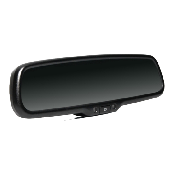
- Page 8 Replacement Monitor The mirror monitor replaces the existing car mirror. Carefully remove the mirror off the “pin”. Slide the replacement mirror on to the pin and secure it with the screw provided (already in the screw hole).Differ- ent cars have different brackets, depending on your vehicle make and manufacturer.
- Page 9 Wiring After connecting the camera to the “camera cable” the camera should be plugged into AV2 input. Connect the RED 12V power wire to a an ignition power source and the BLACK 12V ground wire to a chassis ground. The GREEN wire is the REVERSE trigger wire. Connect this wire to the vehicle’s backup light circuit to activate the rear-view image whenever the vehicle shifts into reverse.
- Page 10 Grid Lines Generally, to help drivers estimate the distance from obstacles, there are three lines for reference- red, yellow, and green. Those three lines are dis- played on the monitor when car is reversing. The green line is 3M from the back of the car and the yellow line is 6.5 ft.
- Page 11 FIGURE 1.1 FIGURE 1.2 Reverse With Confidence ™...
- Page 12 FIGURE 2.1 1. RED- Power (+) 2. YELLOW- Video 3. GREEN- Mirror / Normal Imaging 4. WHITE- Audio 5. BLACK- Ground (-) RVS Systems...
- Page 13 FIGURE 2.2 Reverse With Confidence ™...
-
Page 14: Digital Compass Calibration
Digital Compass Calibration The compass can be calibrated by driving your vehicle in several complete circles. See figures below. If the vehicle’s compass headings become inaccurate, the compass can also be manually calibrated: 1.Press the “MENU” three times to enter into “SETTING” menu, and press “SEL/REC” button to choose the “ANGLE”. - Page 15 5. Press “SEL/REC” to select the “CALIBRATION”, press “UP” “DOWN” , select the “OFF” 1-4 Caution 1. Make sure the rear view mirror is clearly visable to the driver before calibration. 2. Do not calibrate the compass near a large truck. 3.
- Page 16 Q&A Q: Why does the compass need to be calibrated? A: The magnetism of a car is stronger than the magnetism of the Earth. The compass will only function properly if it is calibrated to the magnetic conditions of Earth. Q: Why is compass not accurate in some areas? A: In some areas, such as iron mines, high-intensity magnetic fields change the Earth’s magnetism.
-
Page 17: Temperature Sensor Installation
Temperature Sensor Installation Locate the temperature sensor between the front of the radiator and the front bumper. Slide the metal clip over the edge of the sheet metal or plasic shield until it is secure. Do not install the temperature sensor near the engine. The Distribution Of Magnetic Fluxline We do not recommend using the compass in an area with high magnetic lines of flux. - Page 18 RVS Systems...
- Page 19 Reverse With Confidence ™...
-
Page 20: Specifications
About Our Monitor 10.25” 3” SPECIFICATIONS: Screen Size: 4.3” Display Screen: TFT-LCD Display Resolution: 400(H)x234(V) Aspect Ratio: 16:9 Color Depth: 16.7M dithering Pixel Pitch (mm) 0.219x0.219 Power Consumption: Working Voltage: DC12V VIDEO-IN to GPS/DVD Video Input: (Default) Camera to backup camera Signal System: PAL/Auto/NTSC RVS Systems... - Page 21 No Image On Screen • Do a hard reset, unplug all cables • Verify camera is on correct camera and power cables, leave out for 1 input minute and then re-connect them • Verify cable is connected to • Check to ensure that the monitor connection to the camera is tight •...
-
Page 22: One Year Warranty
ONE YEAR WARRANTY RVS SYSTEMS, INC. WARRANTS THIS PRODUCT AGAINST MATERIAL DEFECTS FOR A PERIOD OF ONE YEAR FROM DATE OF PURCHASE. WE RESERVE THE RIGHT TO REPAIR OR REPLACE ANY SUCH DEFECTIVE UNIT AT OUR SOLE DISCRETION. RVS SYSTEMS, INC. IS NOT RESPON- SIBLE FOR A DEFECT IN THE SYSTEM AS A RESULT OF MISUSE, IMPROPER INSTALLATION, DAMAGE OR MISHANDLING OF THE ELECTRONIC COMPONENTS. - Page 23 DISCLAIMER RVS SYSTEMS AND/OR ITS AFFILIATES DOES NOT GUARANTEE OR PROMISE THAT THE USER OF OUR SYSTEMS WILL NOT BE IN/PART OF AN ACCIDENT OR OTHERWISE NOT COLLIDE WITH AN OBJECT AND/OR PERSON. OUR SYSTEMS ARE NOT A SUBSTITUTE FOR CAREFUL AND CAU- TIOUS DRIVING OR FOR THE CONSISTENT ADHERENCE TO ALL APPLICABLE TRAFFIC LAWS AND MOTOR VEHICLE SAFETY REGULATIONS.
- Page 24 If you have any questions about this product, contact: RVS Systems, Inc. 1797 Atlantic Avenue Brooklyn, NY 11233 800.764.1028 Better Cameras. Better Service. IT’S OUR GUARANTEE. RVS Systems...
Need help?
Do you have a question about the RVS systems RVS-M633 and is the answer not in the manual?
Questions and answers