
Related Manuals for Safe Fleet RVS-619NQ


Summary of Contents for Safe Fleet RVS-619NQ
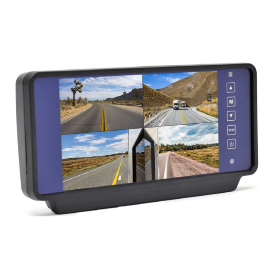
- Page 1 RVS-619NQ Rear View Monitor 7" Quad View Replacement Mirror Monitor Instruction Manual © Rear View Safety 2022...
-
Page 2: Table Of Contents
TABLE OF CONTENTS Introduction ....................3 Safety Information ..................4-6 Before Beginning Installation ..............7 Installation Guide ..................8 Replacement Installation Diagram ............8 Wiring Camera & Monitor ................9-10 Connection Diagram ..................11 Monitor Operation ................12-13 Splitting & Splicing ...................14 Positioning ....................15 Monitor Dimensions ...................16 Monitor Specifications ................17 Troubleshooting ....................18 Warranty ......................19... -
Page 3: Introduction
Congratulations on purchasing a Rear View Backup Camera System! With this manual you will be able to properly install and operate the unit. The Backup Camera System is intended to be installed as a supplement aid to your standard rear view mirror that already exists in your vehicle. The Backup Camera System should not be used as a substitute for the standard rear view mirror or for any other mirror that exists in your vehicle. -
Page 4: Safety Information
SAFETY INFORMATION Please read the entire manual and follow the instructions and warnings carefully. Failure to do so can cause serious damage and/or injury, including loss of life. Be sure to obey all applicable local traffic and motor vehicle regulations as it pertains to this product. - Page 5 SAFETY INFORMATION INSTALLATION Electric shock or product malfunction may occur if this product is installed incorrectly. Use this product within the voltage range specified. Failure to do so can • cause electronic shock or product malfunction. Take special care when cleaning the monitor. •...
- Page 6 If you have questions about this product, please contact us at: 800.764.1028 sales@rearviewsafety.com www.rearviewsafety.com New York 1797 Atlantic Ave Brooklyn, NY 11233 Indiana 319 Roske Dr. Elkhart, Indiana 46516 Canada 68 Trafalgar Square Thornhill, ON, L4J 7M5, Canada IN NO EVENT SHALL SELLER OR MANUFACTURER BE LIABLE FOR ANY DIRECT OR CONSEQUENTIAL DAMAGES OF ANY NATURE, OR LOSSES OR EXPENSES RESULTING FROM ANY DEFECTIVE PRODUCT OR THE USE OF ANY PRODUCT.
-
Page 7: Before Beginning Installation
BEFORE YOU BEGIN INSTALLATION Before drilling please check that no cable or wiring is on the other side of the wall. Please clamp all wires securely to reduce the possibility of them being damaged while vehicle is in use. Keep all cables away from hot or moving parts and electrical noisy components. -
Page 8: Installation Guide
INSTALLATION GUIDE Cable 1. Be sure to position the cable properly. The aviation camera cable uses aircraft grade connectors which means the camera cable can be exposed to all weather elements. Do not run the cable over sharp edges, do not kink the cable and keep away from HOT and rotating parts. -
Page 9: Wiring Camera & Monitor
WIRING CAMERA AND MONITOR The Power Harness • To power the system connect the power (RED) 12V+ wire to ignition power and the ground (BLACK) wire to chassis ground. • These are the only wires needed to power the entire system and all the cameras. - Page 10 WIRING CAMERA AND MONITOR Audio: There is audio on channels 2 and 3. On channel 3 the blue trigger wire must be energized (12V) to activate the audio. On channel 2 the audio is always on. Grid-lines: The grid-lines are also carried through the blue wire. To use the grid-lines for reversing, connect the blue wire to a reverse power.
-
Page 11: Connection Diagram
CONNECTION DIAGRAM Rear View Safety, 1797 Atlantic Ave., Brooklyn NY 11233 800.764.1028 sales@rearviewsafety.com www.rearviewsafety.com... -
Page 12: Monitor Operation
MONITOR OPERATION Use "Contrast", "Brightness", and "Saturation" to adjust the image properties. Use "Language" to change menu and display language. © Rear View Safety... - Page 13 MONITOR OPERATION Use "Display" to select the camera Select a Turn direction channel you want to view to set camera view triggers. Choose what channel the "Reset" will reset all settings Distance Grid will display on. back to factory default. Rear View Safety, 1797 Atlantic Ave., Brooklyn NY 11233 800.764.1028 sales@rearviewsafety.com www.rearviewsafety.com...
-
Page 14: Splitting & Splicing
SPLICING 1. Red - Power (+) 2. Yellow - Video 3. Green - Mirror / Normal Imaging 4. White - Audio 5. Black - Ground (-) © Rear View Safety... -
Page 15: Positioning
POSITIONING Rear View Safety, 1797 Atlantic Ave., Brooklyn NY 11233 800.764.1028 sales@rearviewsafety.com www.rearviewsafety.com... -
Page 16: Monitor Dimensions
MONITOR DIMENSIONS © Rear View Safety... -
Page 17: Monitor Specifications
SPECIFICATION TFT LCD Digital Monitor Digital 7” Screen Size and Type 800H x 3 (RGB) x 480V Dot Resolution 16:9 Display Format 400cd/m Display Brightness 90° min Viewing Angle 4 Channel Video Input 1Vp-p, 75Ω Video Source DC 12V-24V (+/-10%) Power supply Power Consumption -10°C - +65°... -
Page 18: Troubleshooting
TROUBLESHOOTING Monitor Displays Blue Screen & Displays No Signal Do a hard reset, unplug all cables and power cables and leave out for 1 • minute and then re-connect them. Check to ensure that the connection to the camera is tight. •... -
Page 19: Warranty
ONE YEAR WARRANTY REAR VIEW SAFETY, INC. WARRANTS THIS PRODUCT AGAINST MATERIAL DEFECTS FOR A PERIOD OF ONE YEAR FROM DATE OF PURCHASE. WE RESERVE THE RIGHT TO REPAIR OR REPLACE ANY SUCH DEFECTIVE UNIT AT OUR SOLE DISCRETION. REAR VIEW SAFETY, INC. IS NOT RESPONSIBLE FOR A DEFECT IN THE SYSTEM AS A RESULT OF MISUSE, IMPROPER INSTALLATION, DAMAGE OR MISHANDLING OF THE ELECTRONIC COMPONENTS. -
Page 20: Disclaimer
DISCLAIMER REAR VIEW SAFETY AND/OR ITS AFFILIATES DOES NOT GUARANTEE OR PROMISE THAT THE USER OF OUR SYSTEMS WILL NOT BE IN/PART OF AN ACCIDENT OR OTHERWISE NOT COLLIDE WITH AN OBJECT AND/OR PERSON. OUR SYSTEMS ARE NOT A SUBSTITUTE FOR CAREFUL AND CAUTIOUS DRIVING OR FOR THE CONSISTENT ADHERENCE TO ALL APPLICABLE TRAFFIC LAWS AND MOTOR VEHICLE SAFETY REGULATIONS. - Page 21 Rear View Safety, 1797 Atlantic Ave., Brooklyn NY 11233 800.764.1028 sales@rearviewsafety.com www.rearviewsafety.com...
- Page 22 Engineered For Vehicle Safety If you have questions about this product, please contact us at: 800.764.1028 sales@rearviewsafety.com www.rearviewsafety.com New York 1797 Atlantic Ave Brooklyn, NY 11233 Indiana 319 Roske Dr. Elkhart, Indiana 46516 Canada 68 Trafalgar Square Thornhill, ON, L4J 7M5, Canada...
Need help?
Do you have a question about the RVS-619NQ and is the answer not in the manual?
Questions and answers