
Related Manuals for Safe Fleet RVS-082573


Summary of Contents for Safe Fleet RVS-082573
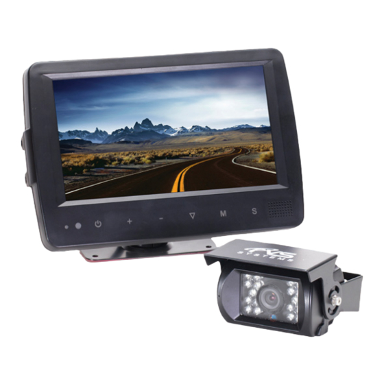
- Page 1 Instruction Manual Backup Camera System with Waterproof Monitor RVS-082573 RVS System, Inc. © 2016 Reverse With Confidence ™...
-
Page 2: Table Of Contents
Introduction....... 03 Safety Information......04-06 Before Beginning Installation . -
Page 3: Introduction
NOTE! Please read all of the installation instructions carefully before installing the product. Improper installation will void manufacturer’s warranty. Congratulations on purchasing a Rear View Backup Camera System! With this manual you will be able to properly install and operate the unit. The Backup Camera System is intended to be installed as a supplement aid to your standard rear view mirror that already exists in your vehicle. -
Page 4: Safety Information
Please read the entire manual and follow the instructions and warnings carefully. Failure to do so can cause serious damage and/or injury, including loss of life. Be sure to obey all applicable local traffic and motor vehicle regulations as it pertains to this product. Improper installation will void manufacturer’s warranty. - Page 5 INSTALLATION: • Electric shock or product or disconnected wire may cause a malfunction may occur if this fire. product is installed incorrectly. • While installing the Rear View System be careful with the wire • Use this product within positioning in order to avoid wire the voltage range specified.
- Page 6 If you have questions about this product, contact: RVS Systems 1797 Atlantic Avenue Brooklyn, NY 11233 Tel: 1.888.881.2601 IN NO EVENT SHALL SELLER OR MANUFACTURER BE LIABLE FOR ANY DIRECT OR CONSEQUENTIAL DAMAGES OF ANY NATURE, OR LOSSES OR EXPENSES RESULTING FROM ANY DEFECTIVE PRODUCT OR THE USE OF ANY PRODUCT.
-
Page 7: Before Beginning Installation
Before drilling please check that no cable or wiring is on the other side of the wall. Please clamp all wires securely to reduce the possibility of them being damaged while vehicle is in use. Keep all cables away from hot or moving parts and electrical noisy components. We recommend doing a benchmark test before installation to insure that all components are working properly. -
Page 8: Installation Guide
Wiring After connecting the monitor to the power harness, plug the camera into the CAM3 input. Connect the RED 12V power wire to an ignition power source and the BLACK 12V ground wire to a chassis ground. The BROWN wire is the REVERSE trigger wire. Connect this wire to the ve- hicle’s backup light circuit to activate the rear view image whenever the vehicle shifts into reverse. - Page 9 Precautions For Use Of Monitor I. The Monitor is made of glass and plastic. Do not subject it to a mechanical shock by dropping it from a high place, etc. II. Do not apply excessive force to the monitor surface or the adjoining areas since this may cause the color tone to vary.
-
Page 10: Accessories
ACCESSORIES RVS Systems... - Page 11 Product Features 1. 7” high resolution TFT LCD color monitor 2. Multiple image options (Horizontal/Vertical/Mirror/Normal) 3. Select from 8 languages 4. Automatic button backlighting and automatic brightness control 5. Full functional remote control 6. Multiple video formats (AUTO/PAL/NTSC) 7. 3 camera inputs 8.
-
Page 12: Monitor Specification
Monitor Dimensions 1. 7” TFT LCD color monitor with a touch screen 2. Audio Output: 1.5W 3. Loudspeaker: One 15x24mm round speaker 4. Power Supply: 10-32V (ignition power source) 5. Power Consumption: ≈6W 6. Monitor Dimensions: 197.2mm (W) × 132mm (H) × 30.5mm (T) 7. -
Page 13: Monitor Installation
Reverse With Confidence ™... -
Page 14: Connections
Connections WHITE / BLUE / BROWN 5 pin male for Camera 1 / Camera 2 / Camera 3. Connect RED 12V power wire to an ignition power source, the BLACK 12V wire to a chassis ground, the BROWN wire to reverse power, the WHITE wire to left turn signal power and the BLUE wire to right turn signal power. -
Page 15: Monitor Buttons
1. Sensor for remote signal 2. Power button 3. Increase / decrease the volume and switch sub-menu values 4. Move menu selection down 5. Menu button 6. Manual camera switch Reverse With Confidence ™... -
Page 16: Remote Operations
Remote Operations MUTE: ENABLE/MUTE sound POWER: Turn monitor on/off : Flip image horizontally RVS Systems... - Page 17 CH: : Flip image vertically CH: Toggle selection up CH: Toggle selection down MENU: Access menu MODE: Toggle picture modes (PERSONAL / STANDARD / SOFT / VIVID / LIGHT) : Decrease brightness : Increase brightness CALL: Display currrent video channel source TIMER: Set a timer to shut down the monitor (10 minute increments, 10-90 minutes) LANG: Change languate...
-
Page 18: Wiring
Connection of AV Adapter and Controller Cable Hold the cable , align the side of jack marked with on the female 13-pin connector with the male 13-pin connector marked with then firmly connect 1. BROWN 5 pin male for Camera1 2. -
Page 19: Trigger Setting
Reversing Display: When the white wire is connected to left turn signal power, the monitor auto- matically switches to CAM1 (left side camera) when the left turn signal is acti- vated. Cam1 When the blue wire is connected to right turn signal power, the monitor auto- matically switches to CAM2 (right side camera) when the right turn signal is activated. -
Page 20: Distance Grid Lines
When the BROWN wire is connected to reverse power, the monitor automati- cally switches to CAM 3 (backup camera) when the vehicle is put into reverse. The distance grid lines will automatically display. AUTOSCAN: When ON, this setting allows the system to automatically switch between connected camera inputs at a predetermined pace. -
Page 21: Menu
Menu Press MENU 1-4 times to display the following options and settings: 1. PICTURE 2. OPTION 3. SYSTEM 4. AUTO SCAN Picture The PICTURE sub-menu inclues BRIGHT, CONTRAST, COLOR, VOLUME, AUTO DIM, and SCALE ADJUST. Reverse With Confidence ™... - Page 22 When AUTO DIM is ON in a dark environment, the on-screen display enters dim mode. When AUTO DIM is turned ON or OFF in a bright environment, the on-screen display remains the same. Dim Mode Normal Mode RVS Systems...
- Page 23 Press to select SCALE ADJUST (ability to adjust grid lines) Reverse With Confidence ™...
- Page 24 OPTION The OPTION sub-menu includes LANG , SCALE , CAM1 , CAM2, and CAM3. RVS Systems...
- Page 25 SYSTEM The SYSTEM sub-menu includes COLOR-SYS, BLUE BACK, HORIZONTAL, VER- TICAL, and ZOOM. Reverse With Confidence ™...
- Page 26 AUTOSCAN The AUTO SCAN sub-meun incldes AUTO SCAN, SCAN TIME, CAM1 , CAM2, and CAM3 RVS Systems...
- Page 27 Camera Dimensions • 18 Infra-red illuminators (enables you to see in total darkness) • 1/4 Sharp® color CCD, 250k pixels, 2.1 mm wide lens with 130° angle • Shock resistant with a 20G Vibration and 100G impact rating • Built-in high gain microphone Reverse With Confidence ™...
-
Page 28: Camera Specification
Camera Specifications SENSOR 1/4” SHARP® COLOR CCD PICTURE ELEMENTS 250,000 PIXELS GAMMA CORRECTION R=0.45 TO 1.0 IMAGE SENSOR 600 TV LINES, PAL: 500 (H) X 582 (V) NTSC: 510 (H) X 492 (V) LENS 2.1MM VIEW ANGLE 130° WATERPROOF RATING IP69K SYNC SYSTEM INTERNAL SYNCHRONIZATION... -
Page 29: Troubleshooting
Troubleshooting Problem Possible Causes/Solutions No picture/sound Adaptor is connected incorrectly. Improper power supply. Unit is off. No picture Check AV cable connection. Audio cable improperly connected. Volume is off or set very low. No sound Dark picture Adjust brightness/contrast. Low environmental temperature. No color Adjust the color settings. -
Page 30: Warranty & Disclaimer
ONE YEAR WARRANTY RVS SYSTEMS, INC. WARRANTS THIS PRODUCT AGAINST MATERIAL DEFECTS FOR A PERIOD OF ONE YEAR FROM DATE OF PURCHASE. WE RESERVE THE RIGHT TO REPAIR OR REPLACE ANY SUCH DEFECTIVE UNIT AT OUR SOLE DISCRETION. RVS SYSTEMS, INC. IS NOT RESPON- SIBLE FOR A DEFECT IN THE SYSTEM AS A RESULT OF MISUSE, IMPROPER INSTALLATION, DAMAGE OR MISHANDLING OF THE ELECTRONIC COMPONENTS. - Page 31 DISCLAIMER RVS SYSTEMS AND/OR ITS AFFILIATES DOES NOT GUARANTEE OR PROMISE THAT THE USER OF OUR SYSTEMS WILL NOT BE IN/PART OF AN ACCIDENT OR OTHERWISE NOT COLLIDE WITH AN OBJECT AND/OR PERSON. OUR SYSTEMS ARE NOT A SUBSTITUTE FOR CAREFUL AND CAU- TIOUS DRIVING OR FOR THE CONSISTENT ADHERENCE TO ALL APPLICABLE TRAFFIC LAWS AND MOTOR VEHICLE SAFETY REGULATIONS.
- Page 32 If you have any questions about this product, contact: RVS SYSTEMS, Inc. 1797 Atlantic Avenue Brooklyn, NY 11233 888.881.2601 Better Cameras. Better Service. IT’S OUR GUARANTEE. RVS Systems...
Need help?
Do you have a question about the RVS-082573 and is the answer not in the manual?
Questions and answers