Table of Contents
Advertisement
Quick Links
Advertisement
Table of Contents

Subscribe to Our Youtube Channel
Related Manuals for ViTiny DiGi UM10


Summary of Contents for ViTiny DiGi UM10
- Page 1 UM10 User’s Guide DiGi Microscope Version 1.0A...
-
Page 3: Table Of Contents
Contents Product Introduction ......2 Packing Contents ......2 Assemble microscope with stand 2 IR Remote Control ....... 4 Microscope Menu Functions ..11 Microscope Introduction: ..24 Microscope Focus ...... 27 Microscope Accessory ....31 Printed Notice ........32 Maintenance ...... -
Page 4: Product Introduction
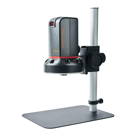
S107 Stand Object Lens 4x Stand assemble guide Object Lens 10x Option Micro SD Card Option Software D/L: www.vitiny.com/vitiny_en/ap_program.html 1.2 Assemble microscope with stand 1.2.1 Fix microscope Tighten the microscope onto stand○ . Refer to Stand assembling instruction for detailed explanation. - Page 5 ○ 1.2.2 Start to use microscope Connect the HDMI cable○ and adaptor○ to HDMI monitor and power. Microscope will turn on when Power in. ○ ○...
-
Page 6: Ir Remote Control
1.2.3 Power On/Off Press Power to turn on microscope. Choose HDMI mode to output image. 1.3 IR Remote Control The microscope operation and functions is controlled by the IR remote control. *Long press means press and hold the button for 2 seconds* (1) Power Turn on/off. - Page 7 :Long Press to switch and enter USB DISK or PC (3) PC CAM CAM mode. See below (16-4) for details. :Press to snapshot or stop video recording; (4) Snapshot Long press to start video recording. (5) LED Adjustment: 12 levels of brightness. :Increase LED brightness.
- Page 8 (9) Exposure Value: 20 levels of exposure value are selectable, from -10~Auto~+9. Increase :Use to increase exposure when the image is (9-1) too dark. :Use to decrease exposure when the image (9-2) Decrease is too bright. :Open/close menu for setting. Menu (10) Menu on Screen function refer to Section 1.4.
- Page 9 : Status bar tells ○ (16) Status Bar Field of View (FOV), Magnification (MAG), and Working Distance (WD) or ON/OFF the status. The area○ e tells the operation status and only show 3 seconds. ○ ○ ○ ○ ○ ○ :...
- Page 10 change depending on the lens position, screen size, and image ratio. (16-1-3) WD: Working Distance. (16-2) Area○ e : (16-2-1) OZ:Optical Zoom. Ex: OZ:500, 500 means sensor position. (16-2-2) SZ:Step Zoom. Ex :SZ : 500. Same format as OZ. (16-2-3) AFS:Single Autofocus. Ex: AFS►A500, “A” means search focus in “current area”, 500 means sensor position.
- Page 11 (16-2-10) FRZ:Image Freeze. Ex: FRZ►ON, means freeze image, FRZ►OFF means unfreeze image. (16-2-11) WB : White Balance Calibration. Ex: WB►SET means calibrate white balance. (16-3) Information○ : IN PCCAM or PLAYBLACK Mode, the shown info are as following: (16-3-1) SNAPSHOT: Take Picture. (16-3-2) REC 00:00:00: Video Recording, each video recording max 30mins.
- Page 12 :SD Card memory. (16-5) SD Card info○ (16-6) Message○ : Show caution information. Ex: when take picture without SD card, the Message will show “No SD Card”. (17) Auto White Balance Calibration : To calibrate the white balance, place the white balance card under the lens, focus until clear, and press AWB.
-
Page 13: Microscope Menu Functions
Microscope Menu Functions Press button to enter Setup, press Up and Down to choose item, Left and Right to turn on/off or adjust parameter. Enter means more functions, press Menu to enter next function or confirm. Return is Return to last page, or press Left or Right to choose “Exit”... - Page 14 (1) Digital Shutter: Digitally control amount of light, the amount is smaller the image is darker and the frame rate is also slower. (2) Video Brightness: Adjust image brightness. (3) D-WDR: Digitally adjusting exposure in areas of the frame to maintain optimum detail in both the shadows and highlights of the image.
- Page 15 1.4.2 BLC Press left/right button to choose turn on/off Backlight compensation mode. (1) OFF :Disable backlight function. (2) BLC (Back Light Compensation) To adjust brightness for darker image in back light environment. (2-1) BLC Gain: To adjust brightness level. (2-2) Area Select: Choose the back light compensation area and size.
- Page 16 1.4.3 Manual WB Calibrate the white light balance, to find out right White color. (1) AWB: Auto white balance. (2) ATW: Trace white area on the sample and auto-calibrated. (3) AWC->SET :Semi-auto white balance. Use to track the white color from current image. (Same as 1.3, (17) operation) (4) MANUAL: Manually adjust blue and red values to find correct white color.
- Page 17 (2) 3D NR: ON/OFF, Motion Adaptive 3D NR. Set Noise Reduction level. RETURN : Choose from RETURN/EXIT (Auto Save Setting) or Return/Exit without Save setting. 1.4.5 SPECIAL Set special functions:...
- Page 18 (1) D-EFFECT : Functions as following: Press Left or right to turn on or off. (1-1) Video Freeze: ON/OFF to freeze image. (1-2) Mirror: Image rotatory. (Horizontal or Vertical) (1-3) Zoom: Digital zoom in the selected area. Zoom size from x1~x4. (1-3-1) Zoom: Select digital zoom.
- Page 19 (1-3-4) RETURN : Choose from RETURN/EXIT (Auto Save Setting) or Return/Exit without Save setting. (1-4) DIS: Digital Image Stabilization function. (1-4-1) LEVEL: Select Stabilization level. (1-4-2) RETURN: Choose from RETURN/EXIT (Auto Save Setting) or Return/Exit without Save setting. (1-5) RETURN: Choose from RETURN/EXIT (Auto Save Setting) or Return/Exit without Save setting.
- Page 20 (2-1) Edit: Delete or add a detective area. (2-2) Sensitivity: The sensitivity to detect whenever object moves. The lower value gets the higher sensitivity. (2-3) DEFAULT: Return to factory setting. (2-4) RETURN: Choose from RETURN/EXIT (Auto Save Setting) or Return/Exit without Save setting.
- Page 21 (3) Crosshair: Set the Horizontal and Vertical Lines on the display. Calibrate the line distances by using calibrator. The calibrated lines can be reference scale. (3-1) Horizontal: (3-1-1) ON/OFF: Display the Horizontal line. (3-1-2) Position: Set the first horizontal line as origin. (3-1-3) Size: Line width.
- Page 22 (3-1-4) Color: Black, White, Yellow, Blue, Green, Pink, Red and Blue. (3-1-5) Count: Show count numbers. Maximum 30 counts. (3-1-6) Spacing: Distance between lines. (3-2) Vertical: (3-2-1) ON/OFF: Display the Vertical line. (3-2-2) Position: Set the first vertical line as origin. (3-2-3) Size: Line width.
- Page 23 DEFFECT: Dead Pixel compensation. (4-1) Live DPC: Dead Pixel Correction. Correct the live dead pixel during preview. Note: Suggest not to change this setting. (4-1-1) LEVEL: Set the threshold value to judge if compensation is needed. (4-1-2) DEAFULT: Return to factory setting (4-1-3) RETURN: Return to last page or Save &...
- Page 24 (4-2-1) LEVEL: Set the threshold value to judge if it needs to be corrected. (4-2-2) DEFAULT: Return to factory setting (4-2-3) RETURN: Choose from RETURN/EXIT (Auto Save Setting) or Return/Exit without Save setting. (6) VERSION: Firmware version. (7) Format SD Card: : Format SD Card when using new one or unable to recognize the current one.
- Page 25 (1) Sharpness: Adjust Sharpness, higher value increases the higher contrast along/near edges of the image. (2) Saturation: Adjust image saturation. (3) Contrast: Adjust image contrast. (4) DEFAULT: Return to factory setting. RETURN: Choose from RETURN/EXIT (Auto Save Setting) or Return/Exit without Save setting. 1.4.7 Video Adjust Reset all parameter to factory setting.
-
Page 26: Microscope Introduction
Microscope Introduction: 1.5.1 IR Remote Area/Indicator When both ○ and ○ LED indicator blinks, the microscope is in standby mode. Caution: Please remove the transparent protection sheet on the IR receiver area. ○ ○ ○ IR remote control aiming area○ The indicator will blink whenever buttons are pressed. - Page 27 Remote control indicator The indicator will lit up when ○ enable Distance Control Toolbar in PC software, lit off when disable the toolbar. 1.5.1 Power/USB/HDMI/Micro SD port Caution: Please hold the cable when remove from microscope and do not disassemble cables forcefully. ○...
- Page 28 (4) Micro SD○ : Insert SD card to save snapshot and video record. 1.5.2 Stand gear box Assemble the stand and then screw the microscope onto the universal joint ○ on the gear box. ○ 1.5.3 LED/ Light socket :Provides luminance for object lens 4x; (1) LED○...
-
Page 29: Microscope Focus
○ ○ Microscope Focus There are two ways to focus. First, choose focus distance to adjust the microscope height, then tuning focus by remote controller until clear. On the contrary, first to choose the image sensor position then adjusts the microscope height. Focus distance: distance from object lens to object. - Page 30 1.6.1 Focus Techniques (1) Fixed focus distance Use knob ○ p or ○ to adjust the distance from the object lens to the object. When the distance is closer, the magnification size is higher. When the focus distance is fixed, use the remote controller or far distance control mode on the application program to focus the image.
- Page 31 ○ ○ 1.6.2 Magnification chart 26 focus section setting is based on the whole focus area per 4x object lens. 10x object lens only have 14 focus sections. The sensor position tells the magnification size(Mag.), field of view(FOV), or working distance(WD). The below chart is measured on 4:3 ratio on 24”...
- Page 32 4X object lens, focus distance from 22mm~214mm(0.866~8.425inch). 4X object lens on 24” (Reference data) Focus section Sensor position 1620 1595 1565 1520 1455 1420 1375 1350 1315 WD(mm) 97.0 86.5 81.5 76.0 FOV(mm) Mag. (X) 13.2 15.1 17.7 21.2 26.5 29.5 33.2 35.4 37.9 Focus section Sensor position...
-
Page 33: Microscope Accessory
10X object lens, focus distance from 6.3mm~10mm(0.248~0.393inch) 10X object lens on 24” (Reference data) Focus section Sensor position 1790 1725 1650 1565 1475 1375 1265 1135 WD (mm) FOV(mm) Mag. (X) Focus section Sensor position WD (mm) FOV(mm) 1.07 Mag. (X) 1.7 Microscope Accessory 1.7.1 White balance card The white side is used to calibrate the white balance. -
Page 34: Printed Notice
Printed Notice Please read the following information before operating. Maintenance Please abide by the following rules while storing or using this product: 2.1.1 Keep dry: do not place the product in a humid environment. Dry surroundings help extend the life of the product. 2.1.2 Avoid temperature shock: temperature shock (for example, taking the product into a warm room from a cold environment) will cause internal condensation inside the machine. -
Page 35: Product Specification
(Output : DC 5.0V/2.0A Input : AC 100-240V Power supplier 50/60Hz) Power 1.6A(Max Current) /8W Consumption (A/C) Size 106(L)×106(W)×152(T) mm Weight Host weight around310 grams Temperature -5℃ ~ 50℃; Humidity-lower than Operation environment 85% (No Condensation) For any changes, please visithttp://www.vitiny.com... -
Page 36: Safety Instructions
Please remove the power supply from the microscope when not in use. Do not disassemble the machine for inspection. For any problems occurring in the machine itself, please power off the device and contact us through e-mail: mltc@vitiny.com... - Page 37 Service fees (including transportation fees) of product inspection. Repair fees. Fees of replaced parts ViTiny Service Center Tel: 07-657-9551 Fax: 07-657-9561 Address: 10 F., No.1, Section 1, Syuecheng Road, Dashu District, Kaohsiung City 840, Taiwan (R.O.C.) Website: http://www.vitiny.com...
- Page 38 ViTiny UM10 Warranty Product Model no S/L nos. Purchase DD/MM/YYYY date Purchaser Tel no: Address Email Distributor Seal for Confirmation ( Stamp is necessary for validation of the Warranty ) ※Distributor’s seal shall include name of the shop, telephone and address※...
- Page 40 HTTP://WWW.VITINY.COM © MicroLinks Technology Corp. All rights reserved.
Need help?
Do you have a question about the DiGi UM10 and is the answer not in the manual?
Questions and answers