Advertisement
Quick Links
Advertisement

Related Manuals for CHIEF CMS445P2


Summary of Contents for CHIEF CMS445P2
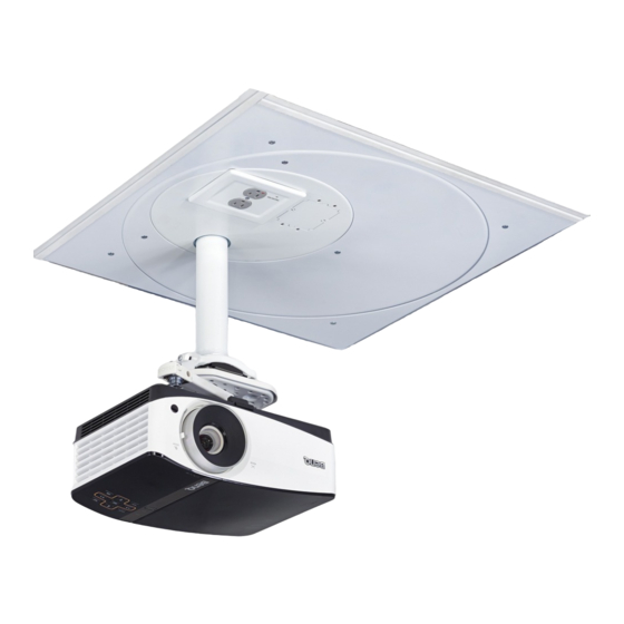
- Page 1 I N S T A L L A T I O N I N S T R U C T I O N S A D D E N D U M Above-Tile and Ceiling Tile Kits Spanish Product Description German Product Description Portuguese Product Description Italian Product Description Dutch Product Description French Product Description CMS445P2...
-
Page 2: Important Safety Instructions
It is the installer’s responsibility to make sure the combined IMPORTANT SAFETY INSTRUCTIONS weight of all components attached to the CMS445P2 does not exceed 50 lbs (22.68 kg). WARNING •... -
Page 3: Installation Instructions
Installation Instructions CMS445P2 LEGEND Tighten Fastener Pencil Mark Apretar elemento de fijación Marcar con lápiz Befestigungsteil festziehen Stiftmarkierung Apertar fixador Marcar com lápis Serrare il fissaggio Segno a matita Bevestiging vastdraaien Potloodmerkteken Serrez les fixations Marquage au crayon Loosen Fastener Drill Hole Aflojar elemento de fijación... -
Page 4: Tools Required For Installation
CMS445P2 Installation Instructions DIMENSIONS - CMS445P2 TOOLS REQUIRED FOR INSTALLATION ADDITIONAL PARTS C (2) B (1) [Screw spacer] D (4) [3/4" mud ring] 06-32 x 1/4" F (1) [Grounding wire] A (1) [CMS445P2] E (1) Earthing symbol IEC 60417 No. 5019 10-32 x 3/8"... - Page 5 If it is not desired to NOTE: use this feature, connect the green/yellow and green wires The CMS445P2 must be connected to a 15 Amp together. branch circuit. IMPORTANT ! : There are two different methods of...
- Page 6 CMS445P2 Installation Instructions Loosen but do not remove two Phillips head screws holding Table 1: Input Specifications outlet box to outer housing. (See Figure 2) Input (view from below) Input voltage, frequency 125 V AC, 60 Hz Input connection type...
- Page 7 Installation Instructions CMS445P2 GREEN (box ground) WHITE BLACK (neutral) (line) Line up hole in outlet cover over light in outlet removed screw GREEN/YELLOW lock washer (isolated ground) (View from underneath) Figure 4 Replace the outlet box in the housing. (See Figure 5)
- Page 8 Figure 11) Use #10-32 x 3/8" flange screw (E) and flathead screwdriver 10. Lower housing from above CMS445P2, install outlet box to attach grounding wire (F) to housing at hole near earthing assembly up into housing, and rotate clockwise into place.
- Page 9 Follow installation instructions (included with the protection circuitry is active and operational. (See CMS445P2) to complete installation. Proceed with Figure 13) Step 12 after the CMS445P2 is installed above the tile. NOTE: Be sure to line up hole in outlet cover over light in outlet.
- Page 10 CMS445P2 Installation Instructions...
- Page 11 Installation Instructions CMS445P2...
- Page 12 A 6436 City West Parkway, Eden Prairie, MN 55344 P 800.582.6480 / 952.225.6000 F 877.894.6918 / 952.894.6918 Europe A Franklinstraat 14, 6003 DK Weert, Netherlands Chief, a products division of P +31 (0) 495 580 852 Milestone AV Technologies F +31 (0) 495 580 845 Asia Pacific A Office No.
Need help?
Do you have a question about the CMS445P2 and is the answer not in the manual?
Questions and answers