Table of Contents
Advertisement
Quick Links
Advertisement
Table of Contents

Related Manuals for Motortech MIC-Marine


Summary of Contents for Motortech MIC-Marine
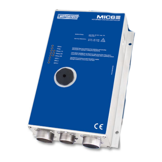
- Page 1 MIC6 – Ignition Controller Operating Manual P/N 01.10.026-EN | Rev. 09/2019...
- Page 2 Information contained in this publication may be changed without prior notice. Trademarks MOTORTECH products and the MOTORTECH logo are registered and/or common law trademarks of the MOTORTECH GmbH. All further trademarks and logos displayed or used in this publication are the property of the respective entitled person.
-
Page 3: Table Of Contents
Table of Contents 1 General Information ....................8 1.1 What Is the Purpose of this Operating Manual? ............8 1.2 Who Is this Operating Manual Targeted to? ............... 8 1.3 Which Symbols Are Used in the Operating Manual? ........... 8 ... - Page 4 Table of Contents 6.1.3 Input Wiring – Pickups ..................42 6.1.4 Input Wiring – Timing and Safety Devices ............45 6.1.5 Output Wiring – Binary Outputs (Go/NoGo, GPO, ASO) ......... 48 6.1.6 Wiring – PowerView3 ..................49 ...
- Page 5 Table of Contents 8.7 Self Test....................... 78 8.8 Pickup Trace ......................79 8.9 Access Control for MIC6 ..................82 8.9.1 Enable/Disable Access Control ................82 8.9.2 Login/Logout ....................83 8.9.3 Changing the PIN ....................83 ...
- Page 6 Table of Contents 8.12.7 Runtime Data – Diagnostics ................141 8.12.8 Runtime Data – Temperatures ................ 143 8.12.9 Runtime Data – Information ................144 8.13 Log ........................145 8.14 Runtime Adjustments ..................146 8.14.1 Runtime Adjustments – Reset ................147 ...
- Page 7 Table of Contents 11 Maintenance ......................170 11.1 Maintenance Instructions ................... 170 11.2 Spare Parts and Accessories ................170 12 Index ........................171 Rev. 09/2019...
-
Page 8: General Information
1 General Information Read through this operating manual carefully before use and become familiar with the product. Installation and start-up should not be carried out before reading and understanding this document. Keep this manual readily available so that you can reference it as needed. 1.1 What Is the Purpose of this Operating Manual? This manual serves as an aid for the installation and operation of the product and supports the technical staff with all operating and maintenance tasks to be performed. -
Page 9: Which Abbreviations/Acronyms Are Used In The Operating Manual
1 General Information Danger This symbol indicates warnings for danger to life, especially due to high voltage. Read these warning notices carefully and take the mentioned precautionary measures. 1.4 Which Abbreviations/Acronyms Are Used in the Operating Manual? In the manual or the user interface, the following abbreviations / acronyms are used. Abb. - Page 10 General Purpose Multi-purpose Output output High Voltage International Organization for Standardization Light Emitting Diode Light emitting electronic semiconductor MOTORTECH Ignition Controller MICT MOTORTECH Software for the configuration Integrated of the MIC6 Configuration Tool MOSFET Metal Oxide Semiconductor component Semiconductor Field-...
-
Page 11: Safety Instructions
Mark the operating location of the ignition system with the corresponding standardized warning symbol. MOTORTECH equipment is manufactured as state of the art and therefore safe and reliable to operate. Nevertheless the equipment can cause risks or damage can occur, if the following instructions are not complied with: –... -
Page 12: Electrostatic Discharge Hazards
2 Safety Instructions – Operate the equipment only while it is in proper condition. – Investigate all changes detected while operating the gas engine or ignition system. – Ensure compliance with all laws, directives, and regulations applicable to the operation of your system, including such not expressly stated herein. -
Page 13: Information On Electric Isolation
2 Safety Instructions 2.3 Information on Electric Isolation If ground and earth potential are not properly isolated, the following problems as well as others can occur: – Electromagnetic interferences (e.g. ground loops) – Signal corruption (e.g. of the analog voltage signal) –... - Page 14 2 Safety Instructions Occurrence of ground loops The devices shown in the following image do not feature the possibility to connect the earth potential and the negative pole of the power supply separated from each other. How ground loops are created. A ground loop is a ground connection of an electric wiring assembly that is closed as a loop.
-
Page 15: Special Safety Instructions For The Device
2 Safety Instructions 2.4 Special Safety Instructions for the Device Danger to life! Hazardous residual voltage! After stopping the ignition, there is dangerous residual voltage for up to three minutes in the ignition system. Do not touch any components of the ignition kit during this time. -
Page 16: Proper Disposal
2.5 Proper Disposal After the expiration of its service life, MOTORTECH equipment can be disposed of with other commercial waste, or it may be returned to MOTORTECH. We will ensure its environmentally friendly disposal. -
Page 17: Intended Use
3 Intended Use 3.1 Functional Description The devices of the MIC6 series are microprocessor controlled ignition systems, each consisting of a board with a 32 bit main processor (CPU). Please note that the manufacturer is not required to implement configurations of the ignition controller for specific engines, and that devices may be delivered without pertinent configuration. -
Page 18: Product Description
4 Product Description 4.1 Technical Data 4.1.1 Certifications The ignition controllers of the MIC6 series are certified as per the following directives/regulations: – EMC Directive 2014/30/EU – EN 61326-1:2013 – Electrical equipment for measurement, control and laboratory use. EMC requirements. General requirements –... - Page 19 4 Product Description Further Approvals for Ignition Controller of the MIC6-Marine Series Lloyd's Register (LR) DNV GL Bureau Veritas (BV) American Bureau of Shipping (ABS) The certificates are included on the storage device enclosed with device. Rev. 09/2019...
-
Page 20: Mechanical Data
4 Product Description 4.1.2 Mechanical Data The MIC6 has the following mechanical characteristics. Feature Value Dimensions 391 mm x 240 mm x 114 mm (15.39" x 9.45" x 4.48") (length x width x height) including connectors MIC6-Marine: Width x height including wire rope dampers: 311 mm x 149 mm (12.22"... -
Page 21: Warning Notices On The Device
4 Product Description 4.1.3 Warning Notices on the Device Validity of warning notices on device The warning notices on the device are valid for the MIC6 and all components connected to it. Warning notice on the device German translation French translation WARNING! Read and WARNUNG! Lesen und ver- ATTENTION! Avant d’installer... -
Page 22: Product Identification - Labeling On The Device
4 Product Description 4.1.4 Product Identification – Labeling on the Device The necessary numbers for unique product identification are on the device: – Part number of the ignition controller (P/N) – Arrangement number of the ignition controller (A/N) – Revision number of the ignition controller indicating its precise construction status (R/N) –... -
Page 23: Electrical Data
4 Product Description 4.1.5 Electrical Data The MIC6 has the following electrical characteristics. Feature Value Power consumption Max. 270 W at 24 V Power supply Nominal voltage: 24 V DC Operating voltage: 16.8 V DC to 32 V DC Required current Max. - Page 24 4 Product Description Electrical Data for Inputs and Outputs The inputs and outputs of the ignition controller have the following electrical data: Inputs and outputs Values Analog current input Current range: 0 mA to 20 mA (adjustable in MICT) Input impedance: 27 Ω || 1 μF Analog voltage input Voltage range: 0 mA to 10 mA (adjustable in MICT) (optional)
- Page 25 4 Product Description Inputs and outputs Values Signal LED Eleven LEDs are used as status indicators. ASO outputs Two auxiliary synchronization outputs TTL level (5 V) max. current: ± 10 mA Pickup input Impedance: 10 kΩ The voltage supply for active pickup can be set using the MICT from 5 V to 24 V.
-
Page 26: Interfaces
4 Product Description 4.1.6 Interfaces Depending on the device version, the following interfaces are available: USB Interface – Compatible with USB 2.0 – The Connector B version is only suitable for temporary data exchange and not for a permanent connection. –... -
Page 27: Overview Drawings
4 Product Description 4.1.8 Overview Drawings The drawings shown correspond to the standard version of the MIC6-Marine with service screw and installed vibration dampers. Plan View Rev. 09/2019... - Page 28 4 Product Description Front View Service Screw Below the service screw are a USB port and a button. Labeling Function USB connection for connecting to the computer Button acknowledges errors, warnings and alarms or triggers a reset of the ignition controller. Please refer also to the notice below. Behavior of the button PB With the PB button on the device you can perform the following actions: –...
-
Page 29: Led Functions
4 Product Description 4.1.9 LED Functions LED functions Status Up to firmware version 1.1.00000: LED flashes green if the device is running with no errors. The LED flashes red if an error has occurred. The LED flashes yellow if a warning has occurred. From firmware version 1.1.00000: LED flashes green if the device is running with no errors. - Page 30 4 Product Description Indication via the Status LED (from firmware version 1.1.00000) The flashing sequences shown below are repeated until the device has left the respective state again. However, the flashing sequences are always executed to the end and are not interrupted accordingly.
- Page 31 4 Product Description The status LED flashes red: Critical error/ Assertion – fast flashing red/off 100 ms – Operating error – General/ System error slow flashing red/off 500 ms – Bootloader – Faulty firmware Flashing one time red 2,000 ms on, 250 ms off –...
-
Page 32: Installation Instructions
5 Installation Instructions 5.1 Unpacking Unpack the equipment, taking care not to damage it, and ensure that the operating manual is always stored with the ignition controller and is easily accessible. Always place the device safely and protected from falling over or falling down as long as it is not fastened to the selected installation location as specified (see Installation of the Ignition Controller on page 33). -
Page 33: Installation Of The Ignition Controller
5 Installation Instructions 5.2 Installation of the Ignition Controller The installation of the MIC6 ignition controller is generally implemented on a fixed bracket e. g. on a wall near the engine. Use the included vibration dampers and the ground strap. The following vibration dampers are included in the scope of supply of the respective devices: MIC6: rubber vibration dampers –... -
Page 34: Installation Of The Vibration Dampers
5 Installation Instructions 5.2.1 Installation of the Vibration Dampers The MIC6-Marine series is supplied with wire rope vibration dampers, which must be used to maintain the permissible vibration conditions. For the MIC6 series devices used for stationary gas engines, the rubber vibration dampers supplied must be used. MIC6-Marine Note that the wire rope vibration dampers have a hole on one side and... - Page 35 5 Installation Instructions MIC6 There are two options for using the vibration dampers from the MIC6's scope of supply. The hole patterns can be found in section Overview Drawings on page 27. Option A Fasten the four vibration dampers to the selected installation location.
-
Page 36: Installation Of The Ground Strap
5 Installation Instructions 5.2.2 Installation of the Ground Strap Fasten the ground strap to the MIC6 ground pin. To do so, use one washer M6 , one tooth lock washer A6 and one poly lock nut M6 2. Connect the ground strap to one of the sides suitable for grounding. -
Page 37: Wiring Of The Device
6 Wiring of the Device 6.1 Input and Output Wiring on the Controller Operational safety! All connector screws and screw joints must be adequately tightened. Refer to the section Mechanical Data on page 20. Assignment of the wire colors Take the assignment of the wire colors of the wiring harness for the input and output wiring from the wiring diagram enclosed with the wiring harness. - Page 38 6 Wiring of the Device 35-Pole Input Connector First input connector (35-pole, outside view) Assignment Assignment L + (24 V) ASO1 + L – (negative pole) ASO Com Pickup 1 Power Pickup 3 Power Signal Signal Shield Shield Pickup 2 Power GPO2 + Signal...
- Page 39 6 Wiring of the Device 26-Pole Input Connector Second input connector (26-pole, outside view) Assignment Assignment RS485 Shield RS485 TX + TX – Pickup 4 Power RX + Signal RX – ASO2 + Shield ASO Com Pickup 5 Power Pickup 6 Power Signal Signal...
-
Page 40: Input Wiring - Power Supply
6 Wiring of the Device 6.1.2 Input Wiring – Power Supply Operational safety! The proper functioning of the device is only guaranteed if the device is operated within the permissible supply voltage range. Therefore, use a power supply in accordance with the specifications in the operating manual. - Page 41 6 Wiring of the Device 35-Pole Input Connector L ≙ 24 V DC (nominal voltage) Variations Battery Generator Control unit Power supply Battery Charger Rev. 09/2019...
-
Page 42: Input Wiring - Pickups
6 Wiring of the Device 6.1.3 Input Wiring – Pickups Example Configuration (Two Pickup Sets each with one Active, two Passive Pickups) Pickup Set 1 (35-Pole Input Connector) Camshaft Crankshaft (Reset) Crankshaft Rev. 09/2019... - Page 43 Crankshaft (Reset) Crankshaft The recommended distance to the triggering is 0.75 mm to 1 mm (0.03" to 0.04") for MOTORTECH pickups. Please note that additional fine-tuning is required for every pickup position due to the different conditions of the engines.
- Page 44 6 Wiring of the Device Allocation of the Wire Colors (Example Configuration) Camshaft Designation Wire color Pickup 1/4 Power Brown Pickup 1/4 Signal black Pickup 1/4 GND blue Pickup 1/4 Shield Shield Crankshaft (Reset) Designation Wire color Flywheel with pin Flywheel with hole Pickup 2/5 Signal White...
-
Page 45: Input Wiring - Timing And Safety Devices
6 Wiring of the Device Aux. pickup supply voltage An auxiliary supply voltage for active pickups can be configured using the MICT. The voltage can be set in the range from 5 V to 24 V and is supplied at the connections Pickup 1 Power to Pickup 6 Power. - Page 46 6 Wiring of the Device Two-Wire Transmitter Four-Wire Transmitter Auxiliary analog input supply voltage An auxiliary supply voltage for the analog inputs can be configured using the MICT. The voltage can be set in the range of 5 to 24 V and is made available on the connection Analog Power.
- Page 47 6 Wiring of the Device Wiring MIC6 ignition controller and DetCon detonation control system The following diagram shows an example of the wiring of a MIC6 ignition controller with a DetCon detonation control system in cases where the analog current signal (4-20 mA) at the output I out is to be used for the ignition timing adjustment.
-
Page 48: Output Wiring - Binary Outputs (Go/Nogo, Gpo, Aso)
6 Wiring of the Device 6.1.5 Output Wiring – Binary Outputs (Go/NoGo, GPO, ASO) Example Configuration *) DetCon or other external device (for wiring of the DetCon, see following example) K1 = Go/NoGo relay K2/K3/K4 = GPO relay L ≙ 24 V DC 35-Pole Input Connector 26-Pole Input Connector Binary output as low-side switch... -
Page 49: Wiring - Powerview3
As shown in the following illustration, you can connect the PowerView3 directly to the MOTORTECH ignition controller using the CAN cable delivered with the PowerView3. To do so, you need to insert the connector in the CAN interface on the PowerView3. On the ignition controller, connect the color-coded conductors of the CAN cable to the correct CAN interface connections. - Page 50 PowerView3 Power Supply via the Ignition Controller If you use a MOTORTECH ignition controller with a service cover and connector strip, you have the option of supplying power to the PowerView3 via the ignition controller. A special connector is included in the PowerView3's scope of supply.
-
Page 51: Output Wiring - Can Bus Interface
6 Wiring of the Device 3. Negative terminal: Disconnect the conductor from the contact and insert it into contact of the connector provided with the PowerView3. 4. Positive terminal: Disconnect the conductor from the contact and insert it into contact of the connector provided with the PowerView3. - Page 52 ® If you require information on the CANopen ® protocol, contact your MOTORTECH contact person. CAN Bus wiring Note the following when connecting the CAN bus: – Each bus end must be fitted with a terminating resistor of 120 Ω (see drawing).
-
Page 53: Output Wiring - Rs485 Interface
6 Wiring of the Device 6.1.8 Output Wiring – RS485 Interface The RS485 interface can be wired as two-wire or four-wire wiring and twisted cables must be used. With both variants the load resistance (R =120 Ω) is the characteristic impedance of the cable. - Page 54 6 Wiring of the Device Connection on the Ignition Controller Wiring of the RS485 interface Follow these instructions for the RS485 interface wiring: – Max. 32 devices can be connected to a bus. – The maximum wire length is 100 m (328') depending on the transfer rate.
-
Page 55: Ignition Coil Wiring
(see section Engine – Parameters on page 89). Conductor cross-section for primary wiring If you do not use a harness manufactured by MOTORTECH, the primary wiring must have a conductor cross-section of 1.5 mm². Rev. 09/2019... -
Page 56: Ignition Coil Wiring For A 35-Pole Connector
6 Wiring of the Device 6.2.1 Ignition Coil Wiring for a 35-Pole Connector The table shows the pole assignments for the output connector. 35-pole output connector (outside view) Pole Output Pole Output Output A1 Output A7 Output B1 Output B7 Output A2 Output A8 Output B2... -
Page 57: Ignition Coil Wiring For 17- And 14-Pole Connectors
6 Wiring of the Device 6.2.2 Ignition Coil Wiring for 17- and 14-Pole Connectors The table shows the pole assignments for the output connector. 17- and 14-pole output connectors (outside view) Pole Output (17-pole) Pole Output (14-pole) Output A1 Output B1 Output A2 Output B2 Output A3... -
Page 58: Straight Order Wiring Of The Ignition Outputs
6.2.3 Straight Order Wiring of the Ignition Outputs Risk of damage to engine If you use MOTORTECH wiring rails for straight order wiring, it is absolutely necessary that they are correctly selected and installed for the respective engine. Even a rotated installation can cause serious damage to the engine, for example. -
Page 59: Straight Order Wiring Of The Ignition Outputs - Overview
6 Wiring of the Device 6.2.4 Straight Order Wiring of the Ignition Outputs – Overview The table contains the allocation of the MIC6 outputs to the cylinders. Output In-line engine V-engine Connector* Coil** Connector* Coil** Output A1 Output B1 Output A2 Output B2 Output A3 Output B3... -
Page 60: Functions
7 Functions The ignition controllers of the MIC6 series include freely configurable safety and auxiliary functions that, amongst others, can shut down the engine in case of fault. Angle indications in the operating manual All angles in this operating manual are given in °crankshaft. Exceptions are clearly identified. -
Page 61: Go/Nogo
7 Functions 7.4 Go/NoGo The binary output (Go/NoGo) is a potential-free output. It is closed during firing and opens when the ignition switches off. The max. switching current is 100 mA. The output can drive an external relay that e.g. opens a gas valve. The following errors can cause the ignition outputs to shut down: –... - Page 62 7 Functions The figure below gives you an overview of the different functions of the timing correction, which will be explained in more detail in the subsequent sections. Functions that can be activated/disabled via the MICT are marked by a switch symbol. Depending on the device version, some functions might not be available.
-
Page 63: Analog Inputs
7 Functions 7.5.1 Analog Inputs The timing point control can be adjusted with a linear current signal. This signal can be supplied, for example, by a potentiometer, a pressure sensor for charging pressure, or a detonation controller. With the analog process signal (current loop signal) at the analog current input, the timing point can be offset in the advanced or retarded direction within a defined range. -
Page 64: Cylinder-To-Cylinder Alignment
7 Functions Configuration examples In this example the analog inputs are configured in the Timing – Analog Inputs window as follows: – Input current: 4-20 mA – Input voltage: 0-5 V Characteristic 4-20 mA / 0-5 V – Ignition timing adjustment toward retarded. -
Page 65: Speed Curve
7 Functions Use of measuring unit Use this setup option only if a suitable measuring unit is available for determining the optimum timing point, so that the result of a change can be assessed immediately. 7.5.3 Speed Curve To optimize the ignition, for example, during the start phase of the engine, a speed curve can be defined for the MIC6 ignition controllers. -
Page 66: Schedules A/B
7 Functions 7.9 Schedules A/B The MIC6 ignition controllers offer two separate schedules for the parameterization of the ignition timing and energy. By closing input Schedule A/B, the listed parameter settings for schedule B can be selected. A possible application for this is e.g. operation with different gases. If only one schedule is configured, this is used regardless of the switch position. -
Page 67: Gpo: General Purpose Outputs
7 Functions – Misfire rate (secondary, all outputs) above threshold – Misfires per second (secondary, all outputs) above threshold – Consecutive misfires (secondary, single output) above threshold A hysteresis can be defined for some alarms. You can configure the alarms with the MICT. Refer to the section Inputs/Outputs –... - Page 68 7 Functions Application of the ASO signal The following example will illustrate the application of the ASO signal: – Four-stroke engine with 6 cylinders – Ignition angle 120° - 120° Synchronization between MIC6 and Valve Controller Ignition angle in ASO signal in Pulse duration in Cyl.
-
Page 69: Ignition Energy
7 Functions 7.13 Ignition Energy The ignition energy can be set separately for the start phase and normal operation. Here different settings can be made for schedules A and B. You can configure the ignition energy with the MICT. Please refer to the section Timing – Schedule A/B –... - Page 70 7 Functions The following functions are available on the different levels: – Level 0 (Read Only) Enables read-only access for all users. – Level 1 (Operator) The user can operate the Alarm Commands, Error Commands, and the Misfire Counter on this level.
-
Page 71: Settings Via The Mict
8 Settings via the MICT MICT is an abbreviation for MOTORTECH Integrated Configuration Tool. With the MICT, you can configure your ignition controller, and you can view and adjust the operating data of your engine. When working with the MICT, you can press the F1 key at any time to access context- sensitive help. -
Page 72: Access Levels In The Mict
8 Settings via the MICT 8.3 Access Levels in the MICT You can open the MICT on your computer via Start -> Programs -> MOTORTECH -> MICT 2.x.x -> MICT 2.x.x. After opening the MICT, select the access level for which you have clearance. The access level controls the options you have at your disposal in the MICT. -
Page 73: Configuration Pages (Overview)
8 Settings via the MICT 8.4 Configuration Pages (Overview) The configuration pages are divided into the following sections: Item no. Area Menu bar Toolbar Navigation bar Configuration section Status bar The functions in the menu bar, navigation bar and the toolbar as well as the configuration section will be described in the following. -
Page 74: Menu Bar And Toolbar
8 Settings via the MICT The status bar provides you with the following information (from left to right): – Status display Indicates whether a connection is established with the device: – Green: Connection established – Red: The connection was interrupted and is being restored –... - Page 75 8 Settings via the MICT Symbol Menu Function Prints the current configuration. File -> Print Prints the configuration to a PDF file. File -> Print To PDF File Opens a print preview of the configuration. File -> Print Preview Exits the MICT. File ->...
- Page 76 8 Settings via the MICT Symbol Menu Function Opens the window Set spark plug operating hours. Device-> Set spark plug operating hours Opens the window Set Engine Operating Hours. Device -> Set engine operating hours Opens the window Set Date and Time, in which you Device ->...
-
Page 77: Online Update Settings
8.6 Online Update Settings Perform regular online updates MOTORTECH is constantly expanding its databases. Perform regular online updates to make optimal use of the opportunities that the MIC6 provides. The MICT uses data from an engine database and a coil database for the configuration. Such data can be updated with automatic online updates. -
Page 78: Self Test
8 Settings via the MICT – Show Log With this button, you can open a window in which the online updates performed are logged. – Update Now With this button, you manually start an online update. 8.7 Self Test Operational safety! If you carry out a self test, it is essential for the gas supply to be switched off and no more residual gas is left in the combustion chamber. -
Page 79: Pickup Trace
8 Settings via the MICT – Active The self test is running. – Ready The ignition controller is ready and the self test can be started. You have the following options: – Cycles Determine whether the self test should run unlimited or be terminated after a defined number of cycles. - Page 80 8 Settings via the MICT Pickup trace Example of a pickup trace for a configuration with two redundant pickup sets, each of them having three pickups: – Pickup input 1/4 (cam): Single event from the camshaft – Pickup input 2/5 (reset): Single event from the crankshaft –...
- Page 81 8 Settings via the MICT There are the following options for the display of the pickup signals: – Zoom In/Out Using the mouse scroll wheel you can zoom in and out of the displayed record range. Alternatively you can also use the plus and minus keys on the keyboard. With the zoom function, you can e.g.
-
Page 82: Access Control For Mic6
8 Settings via the MICT Error Analysis The pickup traces support you, for example, in analyzing the following errors: – Configuration of the pickup does not agree with the wiring (e.g. trigger disc configuration, allocation of the inputs, allocation of the shafts). In this case, you should compare the values configured with the signals recorded (see Engine –... -
Page 83: Login/Logout
8 Settings via the MICT To enable or disable the access control, proceed as follows: Open the input dialog via Device -> Access Control -> Enable or Disable access control. 2. Enter the PIN for the level Master (Level 3). 3. -
Page 84: Reset All Pins
In the menu bar, select the entry Device -> Access Control -> Get reset all PINs request key to open a window with the same name. 2. Send the request key with the serial number to your service contact person at MOTORTECH (refer to Customer Service Information on page 168). This key is valid only for the respective controller and only for a certain amount of time. -
Page 85: Create, Open, Save
8 Settings via the MICT 8.10.1 Create, Open, Save Click on the symbol to create a new configuration and select the corresponding device type. The device type corresponds to the first five digits of the arrangement number, which you can find on a label on your device. Click on the symbol to open a saved configuration. - Page 86 8 Settings via the MICT Compatibility of the configuration files Configuration files are only compatible for the respective device type, even if the file extension is identical. For example, files created for a MIC3 cannot be downloaded to a MIC3+ and vice versa. To use a configuration for another device, the series and the first four digits of the arrangement number must match.
-
Page 87: Upload, Download
8 Settings via the MICT 8.10.2 Upload, Download Click the symbol to upload the current configuration from the MIC6 to the MICT. If applicable, the MICT first establishes a connection to the MIC6 connected. Click on the symbol to download the configuration set in the MICT to the MIC6. This function can only be executed while the ignition is not active. -
Page 88: Configuration
8 Settings via the MICT If you download a configuration into the MIC6 and are notified of functions that are not supported by the MICT, you should check the MIC6 settings. Re-upload the configuration from the MIC6 to the MICT. You can then see which settings are not transmitted to the MICT. Perform a firmware update, if necessary, and/or update your MICT so that you can use all the MIC6 functions without restriction. -
Page 89: Engine - Parameters
8 Settings via the MICT 8.11.1 Engine – Parameters Engine Selection The MICT holds an engine database with data from various manufacturers and model series. Select the desired engine manufacturer, series, and type by clicking on the corresponding fields. Wiring in firing order is assumed as standard. If straight order wiring is supported for the selected engine, the Wiring dialog opens and you have the opportunity to adapt the output configuration. - Page 90 You can use straight order wiring, if: – Wiring takes place via a corresponding MOTORTECH wiring harness and a MOTORTECH wiring rail. The harness is marked with the following information: PLEASE NOTE! The firing order needs to be configured directly in the ignition controller. The ignition coils on the wiring rail are marked with Connector Pin 1 to Connector Pin X.
- Page 91 8 Settings via the MICT Engine database MOTORTECH does not assume liability for the information in the engine database. Please contact MOTORTECH if discrepancies are found. New Engine Configuration Staff with the authorization for the Advanced Service level additionally has the option for entering the engine data manually, i.e., without selecting entries from the engine database.
-
Page 92: Engine - Cylinder Names
8 Settings via the MICT 8.11.2 Engine – Cylinder Names To facilitate the allocation of the cylinders during the configuration of the ignition outputs, you can individually name each cylinder. The schematic representation of the plan view of the selected engine supports you in this. Enter the following settings: –... -
Page 93: Engine - Ignition Outputs
8 Settings via the MICT – currently not used – Show banks in reverse order currently not used 8.11.3 Engine – Ignition Outputs Make adjustments to the following settings as needed: – Number of Outputs Select the number of outputs for the respective output board. –... - Page 94 8 Settings via the MICT Default Application If you select from the engine database, the data stored for the selected configuration are displayed. These data can only be changed by personnel with access to the Advanced Service level. New Engine Configuration If you have created a new engine configuration on the configuration page Engine –...
-
Page 95: Engine - Ignition Coils
MIC6.) Only use measured ignition coils To operate the MIC6, only ignition coil types measured by MOTORTECH may be used. All ignition coils used must correspond to the part number selected in the drop-down list. Different coil types must not be mixed and also no equivalent or replacement types may be used. - Page 96 8 Settings via the MICT Secondary Diagnostics Enabled The secondary diagnosis can be deactivated and activated for ignition coils that support this function. If the ignition coil does not support this function, the secondary voltage estimation calibration and the of the secondary short calibration are not available. Secondary Voltage Estimation Calibration A correction value without units can be set for the secondary voltage estimation for every configured output to increase the accuracy of the secondary voltage estimation for each...
-
Page 97: Engine - Speed Settings
8 Settings via the MICT 8.11.5 Engine – Speed Settings – Ignition Release Enter the release speed for the ignition at which the first ignition is to fire. The value shall not exceed 1/7 of the nominal speed. – Security Speed Enter the security speed (max. -
Page 98: Engine - Pickups - General
8 Settings via the MICT – Max. Power-On Speed Enter the maximum permitted start speed at which the MIC6 starts sending ignition pulses. A value of 6000 rpm is set as the default value: The MIC6 can be activated at the starter speed and immediately send ignition pulses. - Page 99 8 Settings via the MICT – Index/Reset Position Enter the distance between the first event after the set index/ reset marking and top dead center. With the button Adjust, you can enter the measured firing angle for a given nominal value.
-
Page 100: Engine - Pickups - Inputs
8 Settings via the MICT 8.11.7 Engine – Pickups – Inputs – Pickup Set Assign the pickup to pickup set1 or 2. Read the section Redundant Pickup System on page 60 for general information on pickup sets. Rev. 09/2019... - Page 101 8 Settings via the MICT – Type You can select the type of events that will occur on this input for each pickup input. Type and number of events are defined by the discs or ring gears used. If you decide not to use a pickup input, select the entry None from the list.
- Page 102 8 Settings via the MICT – Active/Passive Select the pickup to be used from the pre-defined pick list: Passive passive pickup Active (low) active pickup with high level as quiescent level Active (high) active pickup with low level as quiescent level –...
-
Page 103: Timing - Analog Inputs
8 Settings via the MICT 8.11.8 Timing – Analog Inputs Auxiliary supply voltage Check with the configuration of the analog inputs, that the set auxiliary supply voltage corresponds to your application. Analog Inputs Base Settings The ignition timing adjustment can be made using two analog input signals, which can be set within the following limits: –... -
Page 104: Timing - Schedule A/B - General
8 Settings via the MICT Set the Upper Limit and Lower Limit of the signals corresponding to your connected device. Also, you have the option to enter a Failure Threshold. If the signal does not reach this value, it is classified by the ignition controller as failure (e.g. - Page 105 8 Settings via the MICT Schedule A General Settings The MIC6 offers two schedules for implementing the necessary settings for the timing of the engine. The schedules A and B can be used for dual fuel operation, for example. The system switches between the schedules via the input Schedule A/B.
-
Page 106: Timing - Schedule A/B - Energy
8 Settings via the MICT The first speed point is always set to 0 RPM. All other timing points are assigned with the value by which the signal is to be offset when the respective speed is reached. For the last speed point, the timing of the nominal speed should be entered. -
Page 107: Timing - Miscellaneous
8 Settings via the MICT Normal Operation If the criteria specified for the start phase are exceeded, the settings for normal operation are used by the ignition controller. Make the energy settings the same as for the start phase. Energy Limit You can use the field Energy Limit to limit the output energy made available by the ignition controller. -
Page 108: Inputs/Outputs - Alarms
8 Settings via the MICT You can specify how fast the changes of the timing should be executed. – Maximum Firing Angle Change Per Cycle Specify the maximum degrees per cycle that the ignition timing may be shifted by for both directions, i.e. - Page 109 8 Settings via the MICT – Spark plug operating hours above threshold / below threshold – Warning active – Error active – Temperature above threshold / below threshold – Analog voltage input over threshold / under threshold – Analog current input over threshold / under threshold –...
-
Page 110: Inputs/Outputs - Aso1, Aso2 (Auxiliary Synchronization Outputs)
8 Settings via the MICT – Outputs Activate one or more checkboxes GPO1, GPO2, GPO3 to enable switching of the correspondent general purpose output in case the alarm is triggered. – GPO Settings Configure the general purpose outputs as normally closed or normally open. 8.11.13 Inputs/Outputs –... - Page 111 8 Settings via the MICT – Angle Reference Select from the Angle Reference drop-down list whether the angle shall be based on the absolute angle of the crankshaft or the actual angle depending on global timing. Then, enter the trigger angle for each impulse and the length of the impulse in μs. This setting also determines when ASO signals are generated.
-
Page 112: Inputs/Outputs - Inputs
8 Settings via the MICT ASO signals depending on the ignition release The setting in the drop down list Angle Reference determines when ASO signals are generated: – Actual Angles Depending on Global Timing ASO pulses are only transmitted if ignition is active, indicated by the green status display Firing Active in the window Runtime Data –... -
Page 113: Miscellaneous - Communication
8 Settings via the MICT – CAN reset (1 s pulse), device reset (5 s pulse) This feature allows (e.g. a master control) to trigger a CAN reset and/or a device reset externally using a high impulse. A high impulse of 1 second leads to a reset of the CAN driver and a high impulse of 5 seconds leads to a device reset. - Page 114 8 Settings via the MICT CAN1/2 Clicking on the CAN1 or CAN2checkbox enables or disables the respective CAN interface on the device. – ALL-IN-ONE (J1939)/J1939/CANopen Select the desired protocol, depending on whether you want to set the communication for the ALL-IN-ONE or for another device. For example, for a connection to the PowerView3, select CANopen.
-
Page 115: Miscellaneous - Information
8 Settings via the MICT Information on protocols Please contact your MOTORTECH contact person if you require more information on the CANopen , J1939 and Modbus protocols. ® 8.11.16 Miscellaneous – Information This configuration page can be viewed by all users, but changes can only be made with authorization for the Service access level. -
Page 116: Runtime Data
8 Settings via the MICT Service Contact In this section, individual contact data can be saved that can be called up and displayed via MICT. 8.12 Runtime Data Click on the symbol to open the window Runtime Data. The following sections will give you an overview of the data you can view on the individual tabs. -
Page 117: Runtime Data - Overview
8 Settings via the MICT 8.12.1 Runtime Data – Overview In this screen, you can find the following information: – Speed Indicator (analog) – Red pointer Displays the current registered speed – Yellow pointer Displays the maximum registered speed since last starting the engine –... - Page 118 8 Settings via the MICT – Global Timing Point Digital indication of the current global timing – Operating Hours – Spark Plugs Indicates the current operating hours of the spark plugs – Engine Indication of current operating hours of the engine –...
- Page 119 8 Settings via the MICT – Yellow: The pickup set is being synchronized. – Gray: No signals are received from the pickup set. – Control – Firing Enabled The green status display signals that the firing is active. – Schedule A/B The green status display shows which parameter settings are currently used.
-
Page 120: Runtime Data - Timing
8 Settings via the MICT 8.12.2 Runtime Data – Timing In this view, the system displays all values and settings in the left hand section that influence the timing. On the right, the current input values (e. g. potentiometer, analog current and voltage input), leading to the displayed timing adjustment, are displayed numerically and in bar charts. -
Page 121: Runtime Data - Ignition
8 Settings via the MICT 8.12.3 Runtime Data – Ignition The following information is provided: – Column: Output Designation of the output – Column: Cylinder If cylinder names are assigned, these are displayed. – Column: Estimated Secondary Voltage [kV] Secondary voltage determined by the ignition controller of the respective output. The secondary voltage is used to determine deviations between the individual outputs. -
Page 122: Runtime Data - Bank A And B
8 Settings via the MICT – Column: Misfire The red status display signals a current misfire at the respective output. With a yellow status display at least one misfire has occurred at the respective output since the last reset of the counter. - Page 123 8 Settings via the MICT – Column: Angle Current output firing angle – Column: Min. Spark Duration Minimum spark duration of the outputs – Column: Energy Output Current energy release of the output – Columns: Misfire Status display for the different types of misfires (primary, secondary, open, short circuit). In case of misfire, the respective status display turns red, otherwise it is gray.
-
Page 124: Runtime Data - States
8 Settings via the MICT 8.12.5 Runtime Data – States Status messages are listed in the States view. The following information is provided: – Operating Hours Operating hours counter reading at the time of message – Time Date and time of the message (see following information box) –... - Page 125 8 Settings via the MICT Date and time of ignition controller The date and time can be individually configured for each ignition controller and saved in the device. The device does not adjust automatically for daylight savings time. Hence, deviations may occur between the device time and the time on the computer used to access the device.
- Page 126 The current sensor of output bank name failed. Restart the name failed. ignition controller. If the error occurs again after restarting the device, please contact MOTORTECH. Cylinder individual timing The cylinder-individual offset has reached the set limit limited to range timing 1 ..
- Page 127 Anumber/Bnumber. Anumber/Bnumber was detected. Restart the ignition controller. If the error occurs again after restarting the device, please contact MOTORTECH. Power output (x W) exceeded The power output (x W) exceeded failure threshold (y W) at error threshold limit (y W) at a a supply voltage of z V.
- Page 128 8 Settings via the MICT Status message Description PUnumber: Faulty Signal. Signal The pickup (PUnumber) is supplying a faulty signal. Signal period (x, events counted y) is period (x, events counted y) is too small compared to too small compared to previous previous signal period (z).
- Page 129 8 Settings via the MICT Status message Description PUnumber: Number of events (x) For the pickup (PUnumber) the number of events (x) counted on pickup input counted on pickup input number does not the match the PUnumber does not the match expected value (y).
- Page 130 (y °C) for more than ten minutes. Ensure that there is sufficient air circulation and/or cooling. Temperature sensor failed. The temperature sensor has failed. Restart the ignition controller. If the error occurs again after restarting the device, please contact MOTORTECH. Rev. 09/2019...
-
Page 131: Runtime Data - Message Log
8 Settings via the MICT 8.12.6 Runtime Data – Message Log In the view Message Log, information, warnings, errors and alarms are listed. Information, warnings and errors are specified by the ignition controller, while alarms can be freely configured using the MICT. Refer to the section Inputs/Outputs – Alarms on page 108. Errors and appropriately configured alarms shut down the engine. - Page 132 8 Settings via the MICT – Category Type of message (information, warning, error, alarm) – Message Message text; you can find more information on the message text in the following sections. You have the following options: – Automatic scrolling If this box is checked, the system automatically displays the last list entry until a new event occurs.
-
Page 133: Information
8 Settings via the MICT 8.12.6.1 Information Information Description Access control disabled. The Access control was disabled (see Access Control for MIC6 on page 82). Access control enabled. The Access control was enabled (see Access Control for MIC6 on page 82). All access control PINs reset. - Page 134 8 Settings via the MICT Information Description Firing disabled (Start/Stop In: The firing is disabled, because at least one of the inputs value, CAN: value, RS485: value) (start/stop input, CAN interface, RS485 interface) used for the firing release is disabled. The inputs can have the following values: –...
-
Page 135: Warnings
Secondary diagnosis disabled due to output to output Anumber/Bnumber. Anumber/Bnumber shut off. Check the ignition coil and wiring at the corresponding output. General warning number. General warning number. An undefined warning has occurred. If this occurs repeatedly, please contact MOTORTECH. Rev. 09/2019... -
Page 136: Alarms
8 Settings via the MICT Warning Description Incompatible coil parameters Incompatible coil parameters received. The secondary received, secondary voltage voltage diagnostics have been disabled. This message diagnostics disabled. may appear during an upgrade/downgrade. Check your configuration data and the MICT version being used. Then download the configuration to the device once again. -
Page 137: Failure
General error number. General error number. An undefined error has occurred. Restart the ignition controller. If the error occurs again after restarting the device, please contact MOTORTECH. General error in pickup pre- General error in pickup pre-processing on pickup input processing on pickup input PUnumber. - Page 138 MOTORTECH. Power failure detected on output Power supply fault in output board caused by output Anumber/Bnumber. Anumber/Bnumber was detected. Restart the ignition controller. If the error occurs again after restarting the device, please contact MOTORTECH. Rev. 09/2019...
- Page 139 Temperature sensor of controller The temperature sensor of controller board failed. Restart board failed. the ignition controller. If the error occurs again after restarting the device, please contact MOTORTECH. Temperature sensor of output The temperature sensor of output board failed. Restart board failed.
- Page 140 8 Settings via the MICT Error Description Trigger period (x, triggers counted The trigger period (x, triggers counted y) is not in y) is not in acceptable range acceptable range compared to previous trigger period (z). compared to previous trigger Check the pickups and the corresponding configuration period (z).
-
Page 141: Runtime Data - Diagnostics
8 Settings via the MICT 8.12.7 Runtime Data – Diagnostics The following information is provided: – CAN State The status display indicates the current error handling status of the device for the CAN bus communication: – Error Active The device is in normal status of the bus communication. If an error occurs in the communication, the device sends an active error flag. - Page 142 8 Settings via the MICT – Bus Off The device is disconnected from the CAN bus due to error accumulations in the bus communication. – Controller Board – Supply Voltage Current voltage supply of the controller board. – Pickup Input Pre-Trigger Voltage Current pre-trigger voltage for the pickup inputs (refer to Engine –...
-
Page 143: Runtime Data - Temperatures
8 Settings via the MICT 8.12.8 Runtime Data – Temperatures In the window you receive an overview of the temperatures of the controller board and the output board. The maximum and minimum values are reset at each new start of the ignition controller. -
Page 144: Runtime Data - Information
In this view, you can find an overview of the device and version data. If problems arise, you can print the current runtime data and send them to the MOTORTECH Service Department by fax or as a PDF file by email. For fast support, we will then immediately have all required information. -
Page 145: Log
If the function is active, the view panel focuses on the latest message. – Log level The selection of the log level is specified by MOTORTECH if needed. – Write log to file This checkbox activates or deactivates, respectively, the saving of the logged data in a selected file. -
Page 146: Runtime Adjustments
8 Settings via the MICT 4. Select the level specified by MOTORTECH from the list Log level. 5. Leave the window open. ▸ The log messages are logged both in the window and in the selected file. Date and time of ignition controller The date and time can be individually configured for each ignition controller and saved in the device. -
Page 147: Runtime Adjustments - Reset
8 Settings via the MICT 8.14.1 Runtime Adjustments – Reset The index/reset position can be corrected by 5 °crankshaft (advanced/retarded) while the device is being operated. The correction is made with the buttons: – 0.1 ADV/RET in 0.1° increments to advance or retard –... -
Page 148: Runtime Adjustments - Timing
8 Settings via the MICT 8.14.2 Runtime Adjustments – Timing The global ignition timing position can be corrected by 50 °crankshaft (advanced/retarded) while the device is being operated. The correction is made with the buttons: – 0.1 ADV/RET in 0.1° increments to advance or retard –... -
Page 149: Runtime Adjustments - Energy
8 Settings via the MICT 8.14.3 Runtime Adjustments – Energy The energy settings can be separately adjusted for both schedules. Changes are implemented immediately and stored in the configuration provided in the device. Spark Duration – +/- 1 μs lengthen or shorten in microsecond increments –... -
Page 150: Runtime Adjustments - Secondary Voltage Estimation Calibration
8 Settings via the MICT 8.14.4 Runtime Adjustments – Secondary Voltage Estimation Calibration The secondary voltage estimation can be calibrated in this window when using ignition coils that support this function: A correction value without units can be set for the secondary voltage estimation for every output to increase the accuracy of the secondary voltage estimation for each individual cylinder. -
Page 151: Runtime Adjustments - Secondary Short Calibration
8 Settings via the MICT 8.14.5 Runtime Adjustments – Secondary Short Calibration The starting voltage and sensitivity for the secondary short-circuit detection can be adjusted. Changes are implemented immediately and stored in the configuration provided in the device. Secondary Short Enable Voltage [kV] Set the necessary average ignition voltage required to activate the secondary short-circuit monitoring: –... -
Page 152: Cylinder Individual Offsets
8 Settings via the MICT Adjust the sensitivity of the short-circuit monitoring If a short-circuit is misdiagnosed at a sensitivity of 1.00, the sensitivity must be set to 1.02. If a short-circuit is not detected at a sensitivity of 1.00, the sensitivity must be set to 0.98. - Page 153 8 Settings via the MICT Immediate execution of the changes Please note that changes made to the timing point are executed immediately at the next firing of the corresponding cylinder. The maximum performed change per cycle is however limited by the corresponding setting in the configuration.
-
Page 154: Schedule Curve
8 Settings via the MICT 8.16 Schedule Curve Click on the symbol to open the window Schedule. 8.16.1 Schedule Curve – Simulation The schedule curve visualizes the configurations of the schedules and simulates the influence of the inputs over the speed range. With the optional input fields, you can switch between schedule A and B. - Page 155 8 Settings via the MICT – Analog Current Input Simulation of the analog current input – Control button for adjustments between the configured values (e.g. 0 mA and 20 mA) – Field for manual input of the desired value in mA –...
-
Page 156: Schedule Curve - Runtime Values
8 Settings via the MICT 8.16.2 Schedule Curve – Runtime Values If the checkbox Simulation is unchecked, the Schedule curve window switches to the current runtime data. The following information is provided: – Schedule Displays the currently selected schedule. – Left column: Potentiometer (the MIC6 has no... -
Page 157: Coils
8 Settings via the MICT 8.17 Coils The MICT has a database with technical information on MOTORTECH ignition coils. Open the database as follows: Tools -> Coils You have the option of storing and printing information on the ignition coils present in the database. -
Page 158: General
8 Settings via the MICT 8.17.1 General Details The following information is provided: – Name Coil name – Coil Type ID Used to clearly identify the ignition coil – Data Version Shows data version of the ignition coil selected in the database. The data version of the ignition coil configured in the ignition controller is displayed in the runtime data in the view Ignition (refer to Runtime Data –... - Page 159 8 Settings via the MICT – Illustration of the ignition coil – Information on the conditions under which a secondary diagnosis is possible using the displayed ignition coil. Coil Parameters The following information is provided: – Max. Breakdown Voltage [kV] Displays the permitted value range for the maximum breakdown voltage in kV.
-
Page 160: Min. Energy Limit Curve
8 Settings via the MICT 8.17.2 Min. Energy Limit Curve Min. Energy Limit Curve The curve provides information on the energy in mJ necessary to achieve a certain maximum breakdown voltage in kV. The two vertical bars show the breakdown voltage area, in kV, in which a secondary diagnosis is possible. -
Page 161: Operation
– Were the correct engine, ignition sequence, and output configuration selected? If you are unsure, contact MOTORTECH or the corresponding engine manufacturer. – Ensure that the firing order of the engine and/or the wiring of the output cable harness are carried out correctly. -
Page 162: Firmware Update
Directly from the storage device: Start the exe file in subdirectory Drivers (e.g. CDM v2.10.00 WHQL Certified.exe). ▸ The MOTORTECH Flash Tool is set up. You can now connect your computer to the ignition controller via the USB interface. Rev. 09/2019... - Page 163 9 Operation Menu Bar and Toolbar After launching the MOTORTECH Flash Tool, the following functions are available to you via the icons on the toolbar and the entries in the menu bar: Symbol Menu Function Opens a firmware file. File -> Open Exits the program.
- Page 164 To start a firmware update, proceed as follows: If an MICT is connected with the ignition controller, disconnect this connection. 2. Start the MOTORTECH Flash Tool via Start -> Programs -> MOTORTECH -> MOTORTECH Flash Tool -> x.x.x (e.g. 0.9.00003) -> MOTORTECH Flash Tool.
- Page 165 9 Operation Help with connection problems If a correctly connected device is not found during the automatic search, this can, for example, be because too many communication interfaces are assigned and must be checked. In this case, an interface from the drop- down list Port in the area Connection can be selected and thus specified.
-
Page 166: Errors
10 Errors 10.1 Possible Faults The MIC6 ignition controllers include several safety functions that can shut down the engine in case of fault: – Overspeed protection – External shut-down contact (Start/Stop) – Misfire detection (primary) – Internal failure of the high voltage supply –... -
Page 167: Misfire Detection (Primary)
10 Errors 10.2.3 Misfire Detection (Primary) Misfiring due to an open circuit on the primary side was detected and displayed in the runtime data. Potential Causes – Defect in the output wiring – Ignition coil defective 10.2.4 Pickup Input Errors Faulty input signals from the pickups are detected. -
Page 168: Acknowledging Faults
10.3.2 Customer Service Information You can reach our customer service during business hours at the following phone and fax number, or by email: Phone: +49 5141 93 99 0 Fax: +49 5141 93 99 99 Email: service@motortech.de Rev. 09/2019... -
Page 169: Returning Equipment For Repair/Inspection
Send the device and the return form to one of the two addresses below or to the nearest MOTORTECH representative: MOTORTECH GmbH MOTORTECH Americas, LLC Hogrevestr. 21-23 1400 Dealers Avenue, Suite A 29223 Celle... - Page 170 Service screw: 2.5 Nm to 3 Nm (1.9 lb-ft to 2.2 lb-ft) 11.2 Spare Parts and Accessories For spare parts and accessories for MIC6 ignition systems, please refer to our current product guide, which is available for download on the Internet at www.motortech.de. Rev. 09/2019...
- Page 171 12 Index A D Access Control Declaration of conformity ....... 18 Activate ............. 82 Device Device ............82 Dimension ..........27 Advanced service Disposal ............ 16 Access level ..........72 Electrical data ..........23 Alarm Installation ..........33 Acknowledge ..........131 Mechanical data ........
- Page 172 Overview ..........122 Electrical data ........... 23 MOTORTECH Installation ..........33 Address ..........169 Mechanical data ........20 MOTORTECH Integrated Configuration Tool Return ............. 169 Access level ..........72 Select type ..........85 Design ............73 Start-up ........... 161 Installation ..........71 Switching off ..........
- Page 173 12 Index Part number ..........22 Self Test ..........78, 168 Pickup input Serial number Setting ............98 Device ............22 Pickup sensitivity Service Function ............ 60 Access level ..........72 Setting ............98 Service contact Pickups Setting ............. 115 Calculate frequency ........
- Page 174 12 Index Timing setup Wiring ............45 U Update Process sequence ........162 Connection ..........26 V Voltage input Current value ........... 120 Function ........... 63 Setting ..........103, 104 W Wiring Auxiliary synchronization output ....48 CAN bus ............. 51 Direct ..........
- Page 175 Rev. 09/2019...
Need help?
Do you have a question about the MIC-Marine and is the answer not in the manual?
Questions and answers