
Related Manuals for Motortech VariSCR


Summary of Contents for Motortech VariSCR
- Page 1 VariSCR – Emission Controller Operating Manual P/N 01.50.025 – EN | Rev. 06/2020...
- Page 2 MOTORTECH products and the MOTORTECH logo are registered and/or common law trademarks of the MOTORTECH GmbH. All further trademarks and logos displayed or used in this publication are the property of the respective entitled person and are used for reference purposes only.
-
Page 3: Table Of Contents
Table of Contents 1 General Information ....................6 1.1 What Is the Purpose of this Operating Manual? ............6 1.2 Who Is this Operating Manual Targeted to? ............... 6 1.3 Which Symbols Are Used in the Operating Manual? ........... 6 ... - Page 4 8.6 Manual Valve Adjustment ..................54 8.7 Manual Pump Adjustment ..................54 8.8 Online Update Settings ..................56 8.9 Access Control for the VariSCR Emission Controller ..........57 8.9.1 Enable/Disable Access Control ................57 8.9.2 Login/Logout ....................57 ...
- Page 5 Table of Contents 8.12 Runtime Data ...................... 76 8.12.1 Runtime Data – Overview .................. 78 8.12.2 Runtime Data – Sensors ................... 81 8.12.3 Runtime Data – Dosing Unit ................83 8.12.4 Runtime Data – Trends ..................85 ...
-
Page 6: General Information
1 General Information Read through this operating manual carefully before use and become familiar with the product. Installation and start-up should not be carried out before reading and understanding this document. Keep this manual readily available so that you can reference it as needed. 1.1 What Is the Purpose of this Operating Manual? This manual serves as an aid for the installation and operation of the product and supports the technical staff with all operating and maintenance tasks to be performed. -
Page 7: Which Abbreviations/Acronyms Are Used In The Operating Manual
Electromagnetic Compatibility of electrical or Compatibility electronic equipment items with their surroundings Electrostatic Discharge Light Emitting Diode Light emitting electronic semiconductor Manifold Absolute Pressure Manifold Air Temperature MICT MOTORTECH Integrated Configuration software for Configuration Tool MOTORTECH control units Rev. 06/2020... - Page 8 1 General Information Abb. Term Description Explanation Selective Catalytic Technology for the reduction Reduction of nitrogen oxides in exhaust gases Universal Serial Bus Serial connection system to link a computer to external devices Rev. 06/2020...
-
Page 9: Safety Instructions
2 Safety Instructions 2.1 General Safety Instructions MOTORTECH equipment is manufactured as state of the art and therefore safe and reliable to operate. Nevertheless the equipment can cause risks or damage can occur, if the following instructions are not complied with: –... -
Page 10: Electrostatic Discharge Hazards
2 Safety Instructions – Noise from the system can cause permanent or temporary damage to your hearing. Wear suitable hearing protection at the system. – Your behavior can reduce possible residual risks to a minimum. Observe responsible handling of the gas engine and the gas-carrying system. 2.2 Electrostatic Discharge Hazards Electronic equipment is sensitive to static electricity. - Page 11 2 Safety Instructions Wiring Example Device with Device featuring shielded wires protection class II Occurrence of ground loops The devices shown in the following image do not feature the possibility to connect the earth potential and the negative pole of the power supply separated from each other.
-
Page 12: Special Safety Instructions For The Device
2 Safety Instructions 2.4 Special Safety Instructions for the Device Explosion hazard! Do not disconnect any connectors while the system is live. If the system is located in a hazardous area, there is a risk of explosion. Explosion hazard! Only use the NO sensor for measurement in non-explosive gas mixtures, as explosive gas mixtures can ignite on the hot sensing element. - Page 13 2 Safety Instructions Risk of injury! The VariSCR emission controller is designed for operation in circuits with protected extra-low voltage with safe electrical isolation (PELV). The voltages in these circuits must not exceed 50 V AC or 75 V DC.
-
Page 14: Proper Disposal
2.5 Proper Disposal After the expiration of its service life, MOTORTECH equipment can be disposed of with other commercial waste, or it may be returned to MOTORTECH. We will ensure its environmentally friendly disposal. -
Page 15: Intended Use
The emission controller is configured using a connected computer. The software used for this purpose is also used to display current system data and error messages. 3.2 Applications The full functionality of the VariSCR emission controller can only be guaranteed if the components of the MOTORTECH SCR system are used, consisting of: –... - Page 16 3 Intended Use System Overview (Example) Emission controller VariSCR Engine Dosing unit (incl. pressure and temperature sensor, Master Generator & CHP dosing valve and heating) Control System Pump module AdBlue tank ® and temperature sensor before the SCR catalytic Exhaust tract...
-
Page 17: Product Description
4 Product Description 4.1 Technical Data 4.1.1 Certifications The emission controller VariSCR is certified according to the following directives: EMC Directive 2014/30/EU – EN 61326-1:2013 – Electrical equipment for measurement, control and laboratory use. EMC requirements. General requirements – EN 55011:2009 + A1:2010 – Industrial, scientific and medical equipment. Radio-frequency disturbance characteristics. -
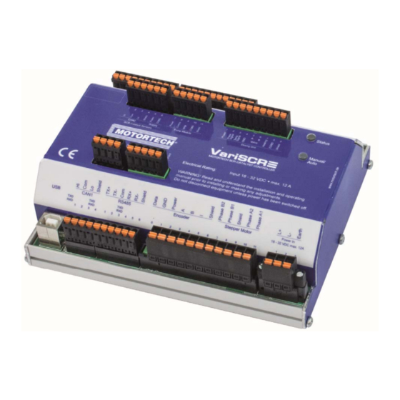
Page 18: Product Identification - Labeling On The Device
Arrangement number of the emission controller (A/N) – Revision number of the emission controller indicating its precise construction status (R/N) (Exemplary representation) 4.1.5 Electrical Data The VariSCR emission controller has the following electrical characteristics: Feature Value Power consumption Max. 180 W... - Page 19 4 Product Description Electrical Data for Inputs and Outputs The inputs and outputs of the emission controller have the following electrical data: Inputs and outputs Values/characteristics Binary inputs – Input voltage up to 32 V DC – Input current at least 5 mA for high level (approx. 12 mA at 24 V DC) –...
- Page 20 4 Product Description Feature Value Output for control signal – Open collector for pump speed – Voltage: 18 V DC to 32 V DC – PWM: 100 Hz – Current: Max. 30 mA Input for feedback signal – NPN with pull-up resistor 12 kΩ for pump speed –...
-
Page 21: Interfaces
4 Product Description Electrical Data of the Connections for the MAP and MAT Sensor The connections of the sensors have the following electrical data: Feature Value Input for the MAP sensor – Permissible current: 4 mA to 20 mA – Measuring range: 0 bar to 3 bar (0 psi to 43.5 psi) –... -
Page 22: Overview Drawings
4 Product Description Field bus protocols No emission-specific values are currently available in the field bus protocols. 4.1.7 Overview Drawings Ports/Connections and LEDs Rev. 06/2020... - Page 23 4 Product Description Designation Function Binary Inputs Binary inputs are available for a reset and a start/stop signal. The Engine Running input can be used to enable the optional mixture control (see Wiring – Binary Inputs on page 36). Binary Outputs The binary outputs signal the status of the emission controller and the SCR catalytic converter (see Wiring –...
- Page 24 Connection for the supply voltage (see Wiring – Power Supply on page 28). This LED lights up if the supply voltage is available. Status signaling The status of the VariSCR emission controller is signaled via the LED Status. – Flashing green: Error-free operation –...
-
Page 25: Installation Instructions
Risk of destruction! Make sure that the device is not covered and ensure sufficient circulation of air. Scope of Supply The scope of supply of the VariSCR emission controller consists of the following components: – Emission controller VariSCR – Storage device (USB flash drive or CD-ROM) including configuration software MICT –... -
Page 26: Wiring
6 Wiring Risk of destruction! The VariSCR emission controller contains separate circuits. If these are connected, this can cause damage to the device. Please adhere to the following points: – The GND connections must not be connected to each other. - Page 27 6 Wiring Wiring of components If you are not using wiring harnesses manufactured by MOTORTECH, carry out the wiring according to the following specifications: – Power supply: 3-wire cable, min. conductor cross-section 1.5 mm², max. cable length 15 m (49') If the cable length is longer, a respective larger cross-section must be selected.
-
Page 28: Wiring - Power Supply
6.1 Wiring – Power Supply Risk of injury! The VariSCR emission controller is designed for operation in circuits with protected extra-low voltage with safe electrical isolation (PELV). The voltages in these circuits must not exceed 50 V AC or 75 V DC. - Page 29 6 Wiring L ≙ 18 V DC to 32 V DC (nominal voltage: 24 V DC) Variations Battery Generator Control unit Power supply Battery Charger Rev. 06/2020...
-
Page 30: Wiring - Sensors On The Scr Catalytic Converter
6 Wiring 6.2 Wiring – Sensors on the SCR Catalytic Converter The sensors before and after the SCR catalytic converter are connected via CAN bus. The pump module is wired using the 6-pole connector in the device cover. To meet EMC requirements, install the control units of the NO sensors and the control unit of the two temperature sensors on an earthed metal plate. - Page 31 6 Wiring Wiring of the sensors on the SCR catalytic converter via CAN When wiring the sensors to the SCR catalytic converter via CAN, observe the following notes: – Each bus end must be fitted with a terminating resistor of 120 Ω (see drawing).
-
Page 32: Wiring - Pump Module
6 Wiring 6.3 Wiring – Pump Module The pump module is wired using the 5-pole connector in the device cover. Designation Function Power Power supply of the pump module Control Control signal for the pump Feedback signal pump speed Ground of the pump module Shield Shield Rev. -
Page 33: Wiring - Dosing Unit
6 Wiring 6.4 Wiring – Dosing Unit The dosing unit is wired using the 9-pole connector in the device cover. Designation Function Power Power supply of the dosing unit Press. Pressure signal Temp. Temperature signal Ground of the dosing unit Valve + Control signal for the dosing valve Valve –... -
Page 34: Wiring - Mat And Map Sensor
6 Wiring Risk of destruction! The VariSCR emission controller contains separate circuits. If these are connected, this can cause damage to the device. Please adhere to the following points: – The GND connections must not be connected to each other. - Page 35 Ground of the pressure sensor Shield Shield of the pressure sensor MAP sensor wiring for V-engines If two VariSCR emission controllers and only one MAP sensor are used for a V-engine, the wiring must be carried out as follows: Rev. 06/2020...
-
Page 36: Wiring - Binary Inputs
6 Wiring 6.6 Wiring – Binary Inputs The binary inputs are wired using the 10-pole connector. The inputs can be switched both on the operating voltage side and on the ground side. L = 5 V DC to 32 V DC Designation Function Start/Stop +... -
Page 37: Wiring - Binary Outputs
6 Wiring 6.7 Wiring – Binary Outputs The binary outputs are wired using the 12-pole connector. The outputs can switch both the operating voltage and the ground. L = 5 V DC to 32 V DC; max. 100 mA Rev. 06/2020... - Page 38 Power – operation. Offline + The output has a low impedance if the VariSCR emission controller is in a state in which the SCR control does not Offline – yet function or only functions to a limited extent (e.g.
-
Page 39: Wiring - Analog Inputs And Outputs
6 Wiring 6.8 Wiring – Analog Inputs and Outputs The analog inputs and outputs are wired using the 8-pole plug. Designation Function 0-10 V U in + currently without function 0-10 V GND 0-20 mA I in + currently without function 0-20 mA I in –... -
Page 40: Wiring - Can Bus
6 Wiring Unused inputs and outputs Please note that the terminals for the analog inputs and outputs not selected in the MICT must remain unoccupied. 6.9 Wiring – CAN Bus The wiring of the CAN bus interface for communication with other devices is done via the 4-pole connector. - Page 41 6 Wiring CAN bus wiring Note the following when connecting the CAN bus: – Each bus end must be fitted with a terminating resistor of 120 Ω (see drawing). – The maximum wire length depends on the bit rate: Bit rate Maximum wire Maximum length Maximum length of...
-
Page 42: Wiring - Modbus (Rs485)
6 Wiring 6.10 Wiring – Modbus (RS485) The Modbus can be wired as half duplex or full duplex, and twisted cables must be used. With both variants the load resistance R is the characteristic impedance of the cable. Wiring Half Duplex First device Last device Second device... - Page 43 6 Wiring Connection to VariSCR emission controller The Modbus is wired using the 6-pole connector. Field bus protocols No emission-specific values are currently available in the field bus protocols. Rev. 06/2020...
-
Page 44: Functions
The pump self test checks whether the pump speed and pump pressure are within the minimum and maximum values specified in the configuration. Two types of pump self test are performed automatically by the VariSCR emission controller: – Initial Self Test The initial self test is performed automatically after starting the emission controller and after each error acknowledgment. -
Page 45: Cooling Of The Dosing Valve
The temperature values at which the heating of the dosing valve is switched on and off can be configured in the MICT. Refer to the section Exhaust Control – SCR – Dosing Valve on page 69. 7.6 Manual and Automatic Operation The VariSCR emission controller can be operated in two modes: – Manual operation –... -
Page 46: Access Control
7.7 Access Control You can protect the VariSCR emission controller against unauthorized access by establishing the access control in the MICT. The access control has four operating levels, three of which can be secured with different PINs. As a default setting, the access control is not activated. If the access control for the emission controller is activated, it is independent from the access levels that control authorizations within the MICT. - Page 47 7 Functions The following functions are available on the different levels: – Level 0 (Read Only) Enables read-only access for all users. – Level 1 (Operator) At this level, the user can carry out manual valve adjustment and manual pump adjustment. Beyond that, he can change the operation mode and can confirm errors.
-
Page 48: Settings Via The Mict
8 Settings via the MICT MICT is an abbreviation for MOTORTECH Integrated Configuration Tool. Use the MICT to configure your VariSCR emission controller. Depending on the version of the MICT you are using, the range of functions may differ from the software version shown. -
Page 49: Access Levels In The Mict
8 Settings via the MICT 8.3 Access Levels in the MICT You can open the MICT on your computer e.g. Via Start -> Programs -> MOTORTECH -> MICT 2.x.x -> MICT 2.x.x. After opening the MICT, select the access level for which you have clearance. The access level controls the options you have at your disposal in the MICT. -
Page 50: Configuration Pages (Overview)
8 Settings via the MICT 8.4 Configuration Pages (Overview) The configuration pages are divided into the following sections: Pos. Area Menu bar Toolbar Navigation bar Configuration section Status bar The functions in the menu, navigation bar, and the toolbar as well as the configuration section will be described in the following. -
Page 51: Menu Bar And Toolbar
– Indication of the access level of the user in the MICT – Indication of the operating level for the VariSCR emission controller if access control has been activated and the user has logged on with a PIN. – Indication of the MICT program version 8.5 Menu Bar and Toolbar... - Page 52 8 Settings via the MICT Symbol Menu Function Changes the access level for accessing the File -> Change Access configuration data and functions. Level Prints the current configuration. File -> Print Prints the configuration to a PDF file. File -> Print To PDF File Opens a print preview of the configuration.
- Page 53 This function is available for certain MOTORTECH Settings -> Display by ignition controllers and has no effect in conjunction cylinders with the VariSCR emission controller. Has no function with the VariSCR emission controller. Document Opens a database with information on MOTORTECH Tools -> Coils ignition coils.
-
Page 54: Manual Valve Adjustment
8 Settings via the MICT 8.6 Manual Valve Adjustment You can manually adjust the dosing valve for optimization or test purposes. In addition, a manual adjustment of the dosing valve is also required to determine the feed forward control characteristic curve. On this, read the section Determine Values for Feed Forward Control on page 98. - Page 55 8 Settings via the MICT Device -> Manual pump adjustment The speed entered in the dialog window is set and held at the start of the test until a timeout occurs or the pressure range configured for the initial pump self test is reached (see Exhaust Control –...
-
Page 56: Online Update Settings
8 Settings via the MICT 8.8 Online Update Settings The MICT uses data from various databases for the configuration. Such data can be updated with automatic online updates. The settings for the update can be entered with the following entry in the menu bar: Settings ->... -
Page 57: Access Control For The Variscr Emission Controller
8 Settings via the MICT 8.9 Access Control for the VariSCR Emission Controller If the access control to the emission controller is activated, access to the following areas is possible with a PIN only: – Troubleshooting – Configuration (Transferring a configuration to the emission controller) The access control regulates the accesses to the emission controller via the MICT. -
Page 58: Changing The Pin
In the menu bar, select the entry Device -> Access Control -> Get reset all PINs request key to open a window with the same name. 2. Send the request key with the serial number to your service contact person at MOTORTECH (refer to Customer Service Information on page 107). This key is valid only for the respective controller and only for a certain amount of time. -
Page 59: Working With Configurations
If the input was correct, all PINs are reset to the default value 0000. 8.10 Working with Configurations To ensure that the VariSCR emission controller interprets incoming data correctly and converts them to the desired control signals, it requires information on the device connected and the master control connected. -
Page 60: Create, Open, Save
8.10.1 Create, Open, Save Click on the symbol to create a new configuration and select the entry Emission Controllers -> VariSCR Standard. Click on the symbol to open a saved configuration. Click on the symbol to save the configuration currently displayed in the MICT to a storage device. -
Page 61: Upload, Download
8.10.3 Compatibility Information If you upload a configuration from the VariSCR emission controller to the MICT that does not correspond to the status of your MICT, or if you open this type of configuration in the MICT, the following situations may occur: –... -
Page 62: Configuration
8 Settings via the MICT 8.11 Configuration The window opens after you select the device type for a new configuration or an existing configuration or have uploaded one from the device. You can make changes to the configuration by selecting an entry from the navigation bar. The corresponding configuration data are then displayed in the configuration section and can be processed. -
Page 63: Inputs/Outputs - Control Setup
To make changes, approval for the access level Advanced Service is required. Selection – Input For the function of the VariSCR emission controller, only the value Exhaust control SCR can be set. – Output Currently no output can be selected. -
Page 64: Exhaust Control - Parameter
8 Settings via the MICT – Enable start/stop enabled Activate the checkbox to enable the binary input Start/Stop on the emission controller. This input is used to start the device from the master control. – External engine running enabled Activate the checkbox to enable the binary input Engine Running on the emission controller. 8.11.2 Exhaust Control –... - Page 65 8 Settings via the MICT – Outlet NO Low Pass Filter Activate this option and enter the cut off frequency. A lower cut off frequency causes the NO sensor to react more slowly. – Catalyst Operating Temperature Range Define the temperature range in which the catalytic converter may be operated. Observe the specifications of the catalytic converter manufacturer.
-
Page 66: Exhaust Control - Scr - Pump Setup
8 Settings via the MICT 8.11.3 Exhaust Control – SCR – Pump Setup Set the following parameters of the pump: PID Controller If necessary, change the basic setting for the PID control of the pump. This can be adjusted during operation via the runtime adjustments (see Runtime Adjustments – Pump on page 93). When you make the settings, you can be supported by the trend views in the runtime data (see Runtime Data –... -
Page 67: Exhaust Control - Scr - Pump Self Test
8 Settings via the MICT Cooling You use the switch-on and switch-off level to define the corresponding limit values for cooling of the dosing valve. When the device is switched off, the pump ensures cooling for the time specified in the corresponding field. 8.11.4 Exhaust Control –... - Page 68 8 Settings via the MICT – Continuous Self Test The continuous self test is performed permanently during operation of the emission controller. Refer to the section Pump Self Test on page 44. You have the following options: – Overall Timeout Enter the total time for the initial self-test, after which the pressure and speed tests must be completed successfully at the latest.
-
Page 69: Exhaust Control - Scr - Dosing Valve
8 Settings via the MICT 8.11.5 Exhaust Control – SCR – Dosing Valve Set the parameters of the dosing valve: PID Controller If necessary, change the basic setting for the PID control of the dosing valve. This can be adjusted during operation via the runtime adjustments (see Runtime Adjustments – Dosing Valve on page 94). -
Page 70: Exhaust Control - Scr - Feed Forward Control
8 Settings via the MICT – Injection Enable Enter the NO value at the intake from which the injection is to take place. – Heater Activate the heater via the corresponding checkbox. You define the respective limit values via the Switch On Level and Switch Off Level. 8.11.6 Exhaust Control –... -
Page 71: Exhaust Control - Check
8 Settings via the MICT On this configuration page you define a characteristic curve for the feed forward control. A maximum of eight points can be configured for this purpose. Each point consists of the dosing rate in dependence of the exhaust gas mass flow. In addition, the maximum dosing rate can also be set for each point of the characteristic curve. - Page 72 8 Settings via the MICT You have the following options: – Intake Limit Set the maximum permissible NO value at the intake. If this value is measured by the NO sensor for longer than the duration specified in the Time field, the emission controller enters the error mode.
-
Page 73: Miscellaneous - Communication
8 Settings via the MICT 8.11.8 Miscellaneous – Communication CAN SCR Catalyst Sensors To connect the catalytic converter sensors, activate the CAN SCR Catalyst Sensors field and select the J1939option. Enter 0 for the Source Address and select the 250 kbit/s Bitrate. Via the field CAN, deactivate or activate the CAN interface of the device. - Page 74 8 Settings via the MICT – Source Address/CANopen Node ID In the protocol ALL-IN-ONE (J1939) and J1939 the source address can be assigned between 0 and 253. In the CANopen protocol, a CANopen node ID from 1 to 127 can be assigned. Note that IDs cannot be assigned more than once.
-
Page 75: Miscellaneous - Service Contact
8 Settings via the MICT Field bus protocols No emission-specific values are currently available in the field bus protocols. 8.11.9 Miscellaneous – Service Contact This configuration page can be viewed by all users, but changes can only be made with authorization for the Advanced Service access level. -
Page 76: Runtime Data
8 Settings via the MICT 8.12 Runtime Data Click on the symbol to open the window Runtime Data. The following sections will give you an overview of the data you can view on the individual tabs. You can print and record the runtime data. For this purpose, the following functions are at your disposal in the toolbar in the window: Symbol Function... - Page 77 8 Settings via the MICT Below the toolbar you will find the most important states and data of your system: – State – Warning The yellow status display indicates that a warning is pending. The currently pending warnings are displayed as a tooltip. Refer to the section Runtime Data – Message Log on page 87.
-
Page 78: Runtime Data - Overview
8 Settings via the MICT 8.12.1 Runtime Data – Overview You can find the following information in the window: Device The status displays provide information on the status of the emission controller. – Warning The yellow status display indicates that a warning is pending. Refer to the section Runtime Data –... - Page 79 8 Settings via the MICT Mode The status displays provide information about the operating mode of the emission controller. – Configured The following status displays are possible: – Green: A valid configuration has been downloaded to the connected emission controller. –...
- Page 80 8 Settings via the MICT – Mode The following status displays are possible: – Green: The feed forward control and the PID control are taken into account. – Yellow: Only feed forward control is taken into account. – Red: An error occurred. –...
-
Page 81: Runtime Data - Sensors
8 Settings via the MICT 8.12.2 Runtime Data – Sensors The window displays detailed information about the sensors used in the SCR system. Basically, the colors of the status displays have the following meaning: – Green: No error – Yellow: Out of the respective value range –... - Page 82 8 Settings via the MICT The following information is displayed in the individual areas of the window: Catalyst Intake Catalyst Outlet For the two NO sensors at the intake and outlet of the catalytic converter, you will receive the following information: –...
-
Page 83: Runtime Data - Dosing Unit
8 Settings via the MICT 8.12.3 Runtime Data – Dosing Unit The window displays detailed information on the dosing unit. Dosing Unit – Pressure Current AdBlue pressure at the dosing valve ® – Temperature Current temperature at the dosing valve Pump –... - Page 84 8 Settings via the MICT Manifold – Pressure Pressure measured by the MAP sensor in the manifold – Temperature Temperature measured by the MAT sensor in the manifold – Exhaust Mass Flow Mass flow equivalent calculated from the measured values of the MAP and MAT sensors. Dosing Unit Controller –...
-
Page 85: Runtime Data - Trends
8 Settings via the MICT 8.12.4 Runtime Data – Trends The trend view shows you the chronological history of essential values of your SCR system. The information provided can help you optimize the PID controllers of the pump and dosing valve. The recording is started as soon as the runtime data window is opened and deleted as soon as the window is closed again. - Page 86 8 Settings via the MICT You have the following options: – Save The recorded values are saved on the connected computer as a CSV file. You can open and process these in other programs such as Microsoft Excel ® – Clear Deletes previously recorded data and starts a new recording.
-
Page 87: Runtime Data - Message Log
The following information is provided: – Operating Hours Operating hours counter reading at the time of message – Time Time and date cannot be shown for VariSCR emission controllers. – Category Message type (information, warning, error) – Message Message text; you can find more information on the message text in the following sections. -
Page 88: Information
8 Settings via the MICT You have the following options: – Automatic scrolling If this box is checked, the system automatically displays the last list entry until a new event occurs. 8.12.5.1 Information Information Configuration changed. Device (firmware version) started at a supply voltage of value. Device switched off. -
Page 89: Errors
Control handler message queue full. SCR pump selftest failure in state. SCR dosing valve failure. Sensor For each error, the status of the VariSCR emission controller at the time the error occurred is provided. Additional parameters are provided if necessary. Rev. 06/2020... -
Page 90: Runtime Data - Diagnostics
8 Settings via the MICT 8.12.6 Runtime Data – Diagnostics In this screen, you can find the following information: Operation Mode The operation mode section shows which operation mode (Manual or Automatic) is currently active and how the operation mode was adjusted. Here, there are the following two options: –... - Page 91 8 Settings via the MICT In this area the current states of the emission controller, the pump and the heating are displayed. These serve as an overview of the overall system. This function is currently not available. Measurements – Supply voltage Current supply voltage of the emission controller –...
-
Page 92: Runtime Data - Information
In this view, you can find an overview of the device and version data. You can also print the current runtime data or, in case of problems, send them to the MOTORTECH Service Department via fax or as a PDF file via e-mail. For fast support, we will then immediately have all required information. -
Page 93: Runtime Adjustments
Runtime adjustments are implemented directly All runtime adjustments are implemented directly without requiring the input to be confirmed and are retained even in the case of a VariSCR emission controller restart. Changes that have been saved in the device configuration are only displayed after re-uploading the device configuration in the MICT's main window. -
Page 94: Runtime Adjustments - Dosing Valve
8 Settings via the MICT The correction of the control is immediately implemented and also remains in place if the device is restarted. The configuration defined in the device is changed directly. 8.13.2 Runtime Adjustments – Dosing Valve The PID control of the dosing valve can be corrected during operation of the device. Use the arrow keys above and below the decimal digit you want to increase or decrease. -
Page 95: Runtime Adjustments - Gas Mixer
8 Settings via the MICT 8.13.3 Runtime Adjustments – Gas Mixer This function is currently not available. 8.14 Log Click on the symbol to open the window Log. This window is only available to users with authorizations starting at the access level Advanced Service. Rev. - Page 96 If the function is active, the view panel focuses on the latest message. – Log level The selection of the log level is specified by MOTORTECH if needed. – Write log to file This checkbox activates or deactivates, respectively, the saving of the logged data in a selected file.
-
Page 97: Operation
2. Set up the AdBlue circuit so that the dosing unit does not overheat. ® 3. Adjust the configuration of the VariSCR emission controller, but first for the feed forward control (configuration page: Exhaust Control –SCR – Feed Forward Control) use the preset values. -
Page 98: Determine Values For Feed Forward Control
Exhaust Control – SCR – Feed Forward Control. Proceed as follows: Start the MICT on your computer and connect to the VariSCR emission controller. 2. Open the supplied Excel file (menue item: Documentation -> VariSCR) on your computer. - Page 99 9 Operation 5. Read off the pressure and temperature in the manifold in the window Runtime Data – Dosing Unit and enter the pressure value in the column MAP and the temperature value in the column MAT in the Excel file.
- Page 100 9 Operation 7. Enter the value in the column NOx inlet of the Excel ® file. Example: 8. Open the dosing valve manually via the menu item Device -> Manual Valve Adjustment until the NO value at the catalytic converter outlet corresponds to the desired final value (e.g. 30 ppm) in the window Runtime Data –...
- Page 101 9 Operation 10. Repeat points 4. to 9. for the remaining seven load points. ▸ The colored (green, yellow, red) columns in the Excel ® file now contain the optimized values for the feed forward control. 11. Enter the values of the colored columns into the configuration page Exhaust Control – SCR – Feed Forward Control in the MICT.
-
Page 102: Firmware Update
A new calibration is then not necessary. 9.2 Firmware Update Using the MOTORTECH Flash Tool, you can update the firmware of your VariSCR emissions controller. The program is provided on the storage device (USB flash drive or CD-ROM supplied). Install MOTORTECH Flash Tool... - Page 103 9 Operation Menu Bar and Toolbar After launching the MOTORTECH Flash Tool, the following functions are available to you via the icons on the toolbar and the entries in the menu bar: Symbol Menu Function Opens a firmware file. File -> Open Exits the program.
- Page 104 To start a firmware update, proceed as follows: If an MICT is connected with the emission controller, disconnect this connection. 2. Start the MOTORTECH Flash Tool via Start -> Programs -> MOTORTECH -> MOTORTECH Flash Tool -> x.x.x (e.g. 0.9.00003) -> MOTORTECH Flash Tool.
- Page 105 9 Operation Help with connection problems If a correctly connected device is not found during the automatic search, this can, for example, be because too many communication interfaces are assigned and must be checked. In this case, an interface from the drop- down list Port in the area Connection can be selected and thus specified.
-
Page 106: Errors
10 Errors 10.1 Troubleshooting If the VariSCR emission controller detects any error, the LED status starts blinking in red. You can find details about status signaling in the following information box. In automatic mode, the binary output Error is also activated in the event of a fault and the corresponding LED lights up. -
Page 107: Acknowledging Faults
10 Errors Overtemperature The temperature of the board of the VariSCR emission controller has been exceeded. Potential causes: – The ambient temperature is too high. – Air circulation around the device is insufficient. 10.3 Acknowledging Faults In manual mode, you have the following options for acknowledging operational errors: –... -
Page 108: Returning Equipment For Repair/Inspection
Send the device and the return form to one of the two addresses below or to the nearest MOTORTECH representative: MOTORTECH GmbH MOTORTECH Americas, LLC Hogrevestr. 21-23 1400 Dealers Avenue, Suite A 29223 Celle... -
Page 109: Maintenance
11 Maintenance 11.1 Spare Parts and Accessories For spare parts and accessories, please refer to our current Product Guide, which is available for you to download on the internet at www.motortech.de. Rev. 06/2020... -
Page 110: Index
12 Index A P Abbreviation ........... 7 Part number ..........18 Advanced service Pump Access level ..........49 Adjustment ..........93 Self test ..........44, 67 C Setting ............66 CAN bus Vent ............54 Configure ..........73 Wiring ............32 Select ............ - Page 111 Rev. 06/2020...
Need help?
Do you have a question about the VariSCR and is the answer not in the manual?
Questions and answers