
Related Manuals for Motortech Varistep


Summary of Contents for Motortech Varistep
- Page 1 VARISTEP – STEPPER MOTOR CARD OPERATING MANUAL MOTORTECH Gas Regulation P/N 01.50.003 – EN | Rev. 07/2013...
- Page 2 © Copyright 2013 MOTORTECH GmbH. All rights reserved. Distribution and reproduction of this publication or parts thereof, regardless of the specific purpose and form, are not permissible without express written approval by MOTORTECH. Information contained in this publication may be changed without prior notice.
- Page 3 TABLE OF CONTENTS 1 General Information ....................6 1.1 What Is the Purpose of this Operating Manual? ............6 1.2 Who Is this Operating Manual Targeted to? ............... 6 1.3 Which Symbols Are Used in the Operating Manual? ........... 6 ...
- Page 4 TABLE OF CONTENTS 7.3 Open/Closed Positions ..................32 7.4 Configurable Opening Angles (Position 1 and 2) ............32 7.5 Change of Openings via Digital and Analog Inputs ..........32 7.6 Analysis of Positions via Analog Outputs..............32 ...
- Page 5 10.3 Acknowledging Faults ..................71 10.4 Customer Service Information ................71 10.5 Returning Equipment for Repair / Inspection ............72 10.6 Instructions for Packaging the Equipment ............72 11 Maintenance ......................73 11.1 Spare Parts and Accessories ................. 73 ...
-
Page 6: General Information
1 GENERAL INFORMATION Read through this operating manual carefully before use and become familiar with the machine. Installation and start-up should not be carried out before reading and understanding this document. Keep this manual readily available so that you can reference it as needed. 1.1 What Is the Purpose of this Operating Manual? This manual serves as an aid for the installation and operation of the product and supports the technical staff with all operating and maintenance tasks to be performed. -
Page 7: Which Abbreviations/Acronyms Are Used In The Operating Manual
Electrostatic Discharge Light Emitting Diode Light emitting electronic semi- conductor MICT MOTORTECH Configuration software for Integrated MOTORTECH control units Configuration Tool Universal Serial Bus Serial wiring system to connect a computer to external equipment Rev. 07/2013... -
Page 8: Safety Instructions
2 SAFETY INSTRUCTIONS 2.1 General Safety Instructions MOTORTECH equipment is manufactured as state of the art and therefore safe and reliable to operate. Nevertheless the equipment can cause risks or damages can occur, if the following instructions are not complied with: –... -
Page 9: Electrostatic Discharge Hazards
2.2 Electrostatic Discharge Hazards Electronic equipment is sensitive to static electricity. To protect these components from damage caused by static electricity, special precautions must be taken to minimize or prevent electrostatic discharge. Observe these safety precautions while you work with the equipment or in its vicinity. –... -
Page 10: Proper Disposal
Always carry or lift the gas mixer by its exterior housing. 2.4 Proper Disposal After the expiration of its service life, MOTORTECH equipment can be disposed of with other commercial waste, or it may be returned to MOTORTECH. We will ensure its environmentally friendly disposal. -
Page 11: Intended Use
3.2 Applications The VariStep stepper motor card can be used for all VariFuel2 gas mixers with stepper motors. If two VariFuel2 gas mixers are being used, two VariStep stepper motor cards are required. An additional splitter is not necessary. -
Page 12: Product Description
4 PRODUCT DESCRIPTION 4.1 Technical Data 4.1.1 Certifications The stepper motor card is certified in accordance with the following standards: – EMC Directive 2004/108/EC – Emission standard for industrial environments as per DIN EN 61000-6-4:2007 – Immunity for industrial environments as per DIN EN 61000-6-2:2006 Rev. - Page 13 DECLARATION OF CONFORMITY The company: MOTORTECH GmbH Hogrevestrasse 21-23 29223 Celle declares that the products: VariStep Stepper Motor Card Intended purpose: to be used on gas-Otto-engines complies with the provisions of the following EC-Directives: EMC Directive 2004/108/EC under consideration of following standards:...
-
Page 14: Mechanical Data
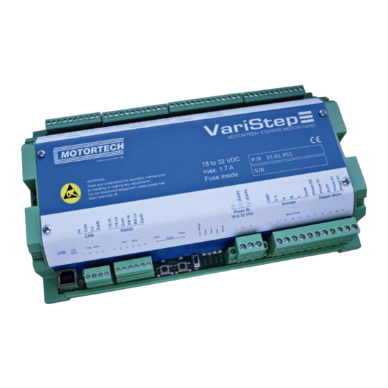
4 PRODUCT DESCRIPTION 4.1.2 Mechanical Data The stepper motor card has the following mechanical characteristics: Feature Value Dimensions 217 x 128 x 50 mm (8.54 x 5.04 x 1.97 '') (length x width x height) Weight 655 g (1.44 lbs) Overview Drawings Shape of device Refer to chapter... -
Page 15: Product Identification – Labeling On The Device
4.1.4 Product Identification – Labeling on the Device The numbers required for unique product identification are on the device: Top of Device Bottom of Device Abb. Meaning Control unit product number Control unit serial number Rev. 07/2013... -
Page 16: Electrical Data
4 PRODUCT DESCRIPTION 4.1.5 Electrical Data The stepper motor card has the following electrical characteristics: Feature Value Power consumption Max. 31 W Power 18 to 32 V DC supply Required current Max. 1.7 A Internal fuse 3.15 A, delay, 5x20 mm, exchangeable Electrical Data for Inputs and Outputs The inputs and outputs of the stepper motor card have the following electrical data: Inputs and outputs... -
Page 17: Interfaces
Inputs and outputs Values/characteristics Digital outputs – Galvanically isolated – Low level: output is high-impedance – High level: output is low-impedance – Switching voltage: maximum 32 V – Current: maximum 500 mA Analog voltage input ( Permissible voltage: 0 to 10 V Input resistance: 12.4 kΩ... -
Page 18: Overview Drawings
4 PRODUCT DESCRIPTION 4.1.7 Overview Drawings Ports/Connections and LEDs Designation Function Digital Inputs Digital inputs via which the fuel ring opening can be modified. There is also a digital input available for a reset signal (refer to Wiring Digital Inputs on page 24). - Page 19 Designation Function Modbus (RS485) Port for communication via Modbus with master control devices. (not yet available) The data transfer is signaled by means of the LEDs =data being sent, =data being received). Open Close Open/Close; buttons can be used to control the stepper Manual and Automatic Operation Reset motor in manual mode (refer to...
-
Page 20: Installation Instructions
ESD standard DIN EN 61340-5-1; VDE 0300-5-1:2008-07. Damages caused by electrostatic discharge are not covered by the guarantee. Scope of Supply The VariStep stepper motor card as supplied consists of the following components: – VariStep stepper motor card – CD-ROM –... -
Page 21: Wiring Of The Control Unit
6 WIRING OF THE CONTROL UNIT 6.1 Wiring Power Supply The power supply is wired using the 3-pole plug. Variations Battery Generator Control unit Supply voltage Battery Charger Rev. 07/2013... -
Page 22: Wiring Stepper Motor And Encoder
6 WIRING OF THE CONTROL UNIT 6.2 Wiring Stepper Motor and Encoder Wiring via the 11-pole plug on the stepper motor card. The length of the connecting cable must not exceed 10 m (32.8 ft). Encoder Stepper motor Rev. 07/2013... - Page 23 Pin assignment when using the original MOTORTECH wiring harness: Pin stepper Pin stepper motor Wire color/ Description motor and card designation encoder Encoder ground Brown Encoder 5V Yellow supply voltage Encoder A White Encoder B Green Encoder I (index) Grey...
-
Page 24: Wiring Digital Inputs
6 WIRING OF THE CONTROL UNIT 6.3 Wiring Digital Inputs The digital inputs are wired using the 10-pole plug. The inputs can be switched both on the side of the operating voltage and on the ground side. 5 – 32 V DC Designation Function DIRin +... -
Page 25: Wiring Digital Outputs
6.4 Wiring Digital Outputs The digital outputs are wired using the 12-pole plug. The outputs can switch both the operating voltage and the ground. 5 – 32 V DC, max. 500 mA Designation Function ERRORout + The output is low-resistance if an error has occurred and the stepper motor card is in automatic mode. -
Page 26: Wiring Analog Inputs And Outputs
6 WIRING OF THE CONTROL UNIT Designation Function POS2out + The output is low-resistance if the stepper motor has reached the configured position 2. POS2out - OFFLINEout + The output is low-resistance if the stepper motor card is in a state in which it does not react to external control signals (e. - Page 27 Designation Function Uin + Voltage input, via which the fuel ring can be adjusted (refer to Inputs / Outputs - Control Setup on page 48). Uin GND Iin + Current input, via which the fuel ring can be adjusted (refer to Inputs / Outputs - Control Setup on page 48).
-
Page 28: Wiring Can Bus
6 WIRING OF THE CONTROL UNIT 6.6 Wiring CAN Bus The CAN bus 2.0B interface is currently not yet available. The CAN bus interface is wired using the 4-pole plug. First device Second-to-last device Second device Last device CAN bus wiring Note the following when connecting the CAN bus: –... -
Page 29: Wiring Modbus
6.7 Wiring Modbus The Modbus interface is currently not yet available. The Modbus can be wired as half duplex or full duplex, and twisted cables must be used. In both models, the load resistance R matches the wave impedance of the cable. Wiring Half Duplex First device Last device... - Page 30 6 WIRING OF THE CONTROL UNIT Port on Stepper Motor Card The Modbus is wired using the 6-pole plug. Rev. 07/2013...
-
Page 31: Functions
7 FUNCTIONS 7.1 Manual and Automatic Operation The opening in the fuel ring can be adjusted via the stepper motor card in two operation modes: – manual operation – automatic operation Auto/Manual You can switch from manual to automatic mode using the switch or via the MICT. -
Page 32: Open/Closed Positions
7 FUNCTIONS 7.3 Open/Closed Positions The open and the closed position are specified as follows: Open – : Openings of the fuel ring are completely open (100% open) Closed – : Openings of the fuel ring are completely closed (0% open) OPENout CLOSEout When one of the two positions is reached, the relevant digital output... -
Page 33: Access Control
7.7 Access Control You can protect the control unit of your VariFuel2 against unauthorized access by establishing the access control in the MICT. The access control has four operating levels, three of which can be secured with different PINs. As a default setting, the access control is not activated. If the access control for the control unit is activated, it is independent from the access levels that control the views within the MICT. - Page 34 7 FUNCTIONS The following functions are available on the different levels: – Level 0 (Read Only) Enables read-only access for all users. – Level 1 (Operator) At this level, the user can change the positions of the fuel ring (approach closed and open position, position 1 and position 2, and make manual changes to the opening).
-
Page 35: Settings Via The Mict
8 SETTINGS VIA THE MICT 8.1 MICT System Requirements For the installation of the MICT, the following minimum requirements must be fulfilled: – x86-compatible PC, minimum performance category Intel Pentium 4 with 2 GHz – 128 MB free RAM – 100 MB free disk space –... -
Page 36: Access Levels In The Mict
8 SETTINGS VIA THE MICT 8.3 Access Levels in the MICT Start -> Programs -> MOTORTECH -> MICT -> MICT Open the MICT on your PC using After opening the MICT, select the access level for which you have clearance. The access level controls the options you have at your disposal in the MICT. -
Page 37: Configuration Pages (Overview)
– Indication of the access level of the user in the MICT – Indication of the operating level for the VariStep if access control has been activated and the user has logged on with a PIN – Indication of the MICT program version... -
Page 38: Menu Bar And Toolbar
Runtime Data page 55. Opens a saved recording of pickup signals File -> Open pickup trace (putrace file), for example from a MOTORTECH ignition controller. Pickup signals cannot be recorded with the VariStep. Changes the access level for accessing the File ->... - Page 39 Symbol Menu Function Downloads configuration data from the PC to Device -> Download to device the device. This function can only be executed in manual mode. Uploads configuration data from the device to Device -> Upload from device the PC. Runtime Data.
- Page 40 MICT. This function is available for certain Settings -> Display by cylinders MOTORTECH ignition controllers and has no effect in conjunction with the VariStep. Has no function with the VariStep. Document Opens the online help function.
-
Page 41: Online Update Settings
8.6 Online Update Settings The MICT uses data from a VariFuel database for the configuration. Such data can be updated with automatic online updates. The settings for the update can be entered with the following entry in the menu bar: Settings ->... -
Page 42: Access Control Of Control Unit
8 SETTINGS VIA THE MICT 8.7 Access Control of Control Unit If the access control to the control unit is activated, access to the following areas is possible with a PIN only: – Troubleshooting – Position changes (Open, Close, Position 1 and 2, Manual Adjustment, Reference Run) –... -
Page 43: Login/Logout
8.7.2 Login/Logout If the access control is activated, you are prompted to log in if you want to execute functions that are allocated to a specific operating level. In addition, you can log in specifically to an operating level via the menu bar. To log into a specific operating level, proceed as follows: Device->... -
Page 44: Resetting All Pins
From the menu bar, select the entry Device -> Access Control -> Get reset all PINs request key to open a window with this name. 2. Send the request key with the serial number to your service contact partner at MOTORTECH Customer Service Information (refer to on page 71). -
Page 45: Selecting The Device Type
8.8 Selecting the Device Type VariStep VariFuel2 Click on the symbol to start a new configuration and select as the device type. 8.9 Opening an Existing Configuration File Click on the symbol to open an existing configuration file. 8.10 Configuration The window opens after you select the device type for a new configuration or an existing configuration or have uploaded one from the device. -
Page 46: External Device
8 SETTINGS VIA THE MICT 8.10.1 External Device Advanced Service To change the VariFuel2 type, access to the level is required. VariFuel2 Use the drop-down list to select the VariFuel2 type that matches the device that you wish to configure. Note the stepper motor revision when making your selection. Note the stepper motor revision The revision of the stepper motor can be identified from the nameplate on the stepper motor of your VariFuel2. - Page 47 Changing the VariFuel2 type Scenario: You have replaced one VariFuel2 gas mixer with another VariFuel2 type. Problem: Upon connection of the new VariFuel2, the control unit will perform a reference run. However, since this configuration still contains data from the first VariFuel, it is possible that the VariFuel2 may leave the traversing range and be mechanically damaged as a result, or it may be necessary to readjust the VariFuel2.
-
Page 48: Inputs / Outputs - Control Setup
8 SETTINGS VIA THE MICT 8.10.2 Inputs / Outputs - Control Setup The settings on the configuration page depend on the inputs and outputs used by your master control. In this case please refer to all information given in the relevant documentations of the Advanced Service control units. - Page 49 Input Voltage/Input Current Depending on which input is selected, you have different adjustment options available. For the analog inputs, please enter the values for the open and closed position of the fuel ring. Here, please adhere to the following values: –...
- Page 50 8 SETTINGS VIA THE MICT Settings of the input selected Analog Inputs (Current or Voltage) Based on the values used by your master control, you can define the values of the open and the closed position for the analog inputs in the MICT. The value applied on the input will then be converted to the relevant opening angle of the fuel ring proportional to the values entered.
-
Page 51: Positions – Values
8.10.3 Positions – Values Position 1/Position 2 You can define two configurable positions using these two input fields. This requires access to Service Advanced Service the access level . Please enter the desired opening angle of the fuel ring as percentage (100% refers to open, 0% refers to closed). The openings named here can be set using the MICT or the digital inputs of the control unit. -
Page 52: Miscellaneous – Communication
8 SETTINGS VIA THE MICT 8.10.4 Miscellaneous – Communication The two interfaces are currently not yet available. The CAN and the Modbus interface cannot be activated simultaneously. CAN enabled enables or disables the CAN interface on the device. Clicking on the field –... - Page 53 Modbus Modbus enabled Clicking on the field enables or disables the Modbus interface on the device. – ASCII/RTU Define whether data is transferred in ASCII or RTU mode. – none/even/odd Define whether a parity bit is used and if the parity is to be even or odd. –...
-
Page 54: Miscellaneous – Service Contact
8 SETTINGS VIA THE MICT 8.10.5 Miscellaneous – Service Contact This configuration page can be viewed by all users, but changes can only be made with Service authorization for the access level. Service Contact In this area, you can store individual contact data. Rev. -
Page 55: Runtime Data
8.11 Runtime Data Runtime Data Click on the symbol to open the window . The following sections will give you an overview of the data you can view on the individual tabs. You can print and record the runtime data. For this purpose, the following functions are at your disposal in the toolbar in the window: Symbol Function... -
Page 56: Runtime Data – Overview
8 SETTINGS VIA THE MICT 8.11.1 Runtime Data – Overview In this screen, you can find the following information: Reference Run The status display provides information on the reference run: – Green: The reference run was completed successfully. – Yellow: The reference run is being carried out. –... - Page 57 Stepper Motor The status display indicates the condition of the stepper motor: – Green: The stepper motor is ready. – Yellow: The stepper motor is active. – Red: An error occurred. Warning/Error A red status display indicates that an error or a warning message occurred. The display will go Device ->...
-
Page 58: Runtime Data – Warnings
8 SETTINGS VIA THE MICT 8.11.2 Runtime Data – Warnings The following information is provided: – Time Stamp Status of the operating hours counter at which the warning occurred. – Warning Id The warning ID is used to identify the warning. –... -
Page 59: Runtime Data – Errors
You have the following options: – Update Update With the button, you can manually update the warning list displayed. If a warning occurs, the list is updated automatically. – Show in reverse order Activate the checkbox to reverse the order of the listed entries. –... - Page 60 8 SETTINGS VIA THE MICT – Error Short description of the error. The following errors are possible: Errors Description Interframe Step Loss Step losses due to rough-running gas mixer Solution: Check if gas mixer moves stiffly or if belt tension is too high. Stop Step Loss Step losses due to rough-running gas mixer Solution:...
-
Page 61: Runtime Data – Diagnostics
– Show only current entries Activate the checkbox to only show the entries which are still up-to-date. 8.11.4 Runtime Data – Diagnostics In this screen, you can find the following information: Operation Mode Manual Automatic Operation The operation mode section shows which operation mode ( Mode ) is currently active and how the operation mode was adjusted. - Page 62 8 SETTINGS VIA THE MICT States This area shows the current conditions of the control unit, the stepper motor and all individual phases of the reference run. CPU Load Current capacity utilization of the processor. Supply Voltage Current supply voltage of control unit. Current Temp Current temperature of board.
-
Page 63: Runtime Data – Information
In this view, you can find an overview of the device and version data. You can also print the current runtime data or, in case of problems, send them to the MOTORTECH Service Department via fax or as a PDF file via e-mail. For fast support, we will then immediately have all required information. - Page 64 If the function is active, the view panel focuses on the latest message. – Log level The log level to be selected will be specified as required by MOTORTECH. – Write log to file This checkbox activates or disables, respectively, the saving of the logged data in a selected file.
- Page 65 If the file does not yet exist, it is automatically created with the extension Write log to file 3. Activate the checkbox Log level 4. Select the level specified by MOTORTECH from the list. 5. Leave the window open. ▸...
-
Page 66: Operation
3. If not already done, install the USB driver by running the file CDM20824_Setup.exe (e. g. ) from the CD-ROM. ▸ The MOTORTECH Flash Tool is now set up. You can connect your PC to the control unit via the USB interface. Rev. 07/2013... - Page 67 Menu Bar and Toolbar After launching the MOTORTECH Flash Tool, the following functions are available to you via the icons on the toolbar and the entries in the menu bar: Symbol Menu Function Opens a firmware file. File -> Open Exits the program.
- Page 68 , check that the device has been recognized correctly. ▸ If the MOTORTECH Flash Tool does not recognize a device that is connected to your PC via the USB interface, you can usually still carry out a firmware update. To do so, observe the instructions in the information windows of the MOTORTECH Flash Tool for the following steps.
- Page 69 Help with connection problems If a correctly connected device is not found during the automatic search, this can, for example, be because too many communication interfaces are assigned and must be checked. In this case, an interface from the drop- Port Connection down list...
-
Page 70: Disturbances
10 DISTURBANCES 10.1 Troubleshooting status If the stepper motor card detects an error, the LED will flash red. In automatic mode, the ERRORout digital output is also activated and the corresponding LED lights up. Using the MICT you can see the type of error occurred. For further information, please refer to the section Runtime Data –... -
Page 71: Acknowledging Faults
10.4 Customer Service Information You can reach our customer service during business hours at the following phone and fax number, or by e-mail: Tel. +49 5141 9399 0 +49 5141 9399 99 E-mail service@motortech.de Rev. 07/2013... -
Page 72: Returning Equipment For Repair / Inspection
Send the device and the return form to one of the two addresses below or to the nearest MOTORTECH representative: MOTORTECH GmbH MOTORTECH Americas, LLC Hogrevestrasse 21–23 1400 Dealers Avenue, Suite A 29223 Celle... -
Page 73: Maintenance
11 MAINTENANCE 11.1 Spare Parts and Accessories For spare parts and accessories, please refer to our current Product Guide, which is available for www.motortech.de you to download on the Internet at Rev. 07/2013... -
Page 74: Index
Update ............41 Configure ..........52 Modbus Wiring ............28 Configure ..........52 Closed position Wiring ............29 Approach ..........38 MOTORTECH Function ........... 32 Address ............ 72 Control unit O Electrical data ........... 16 Installation ..........20 Open position Interfaces .......... - Page 75 Repair ............72 Return shipment ..........72 Runtime data Overview ........... 56 Print ............55 S Safety instructions ......... 8 Service Access level ..........36 Service contact Setting ............54 Software Access level ..........36 Design ............37 Installation ..........35 Menu overview ..........
- Page 76 WE UPGRADE GAS ENGINES Original MOTORTECH Accessories for Stationary Gas Engines As a supplier, MOTORTECH develops, produces and distributes accessories as well as spare and wearing parts for nearly all kinds of stationary gas engines worldwide: Ignition control and monitoring, industrial spark plugs and high tension leads, wiring systems and gas regulation –...
Need help?
Do you have a question about the Varistep and is the answer not in the manual?
Questions and answers