Table of Contents
Advertisement
Quick Links
Advertisement
Table of Contents

Subscribe to Our Youtube Channel
Related Manuals for Motortech MIC100


Summary of Contents for Motortech MIC100
- Page 1 MIC100 – Ignition Controller Operating Manual P/N 01.10.044-EN | Rev. 05/2020...
- Page 2 MOTORTECH products and the MOTORTECH logo are registered and/or common law trademarks of the MOTORTECH GmbH. All further trademarks and logos displayed or used in this publication are the property of the respective entitled person and are used for reference purposes only.
-
Page 3: Table Of Contents
Table of Contents 1 General Information ..................... 7 1.1 What Is the Purpose of this Operating Manual? ............7 1.2 Who Is this Operating Manual Targeted to? ............... 7 1.3 Which Symbols Are Used in the Operating Manual? ........... 7 ... - Page 4 8.5 Menu Bar and Toolbar................... 57 8.6 Online Update Settings ..................60 8.7 Self Test ......................61 8.8 Access Control for MIC100 ..................62 8.8.1 Enable/Disable Access Control ................62 8.8.2 Login/Logout ....................63 ...
- Page 5 Table of Contents 8.10.1 Engine – Parameters ..................69 8.10.2 Engine – Ignition Outputs ................. 72 8.10.3 Engine – Ignition Coils ..................73 8.10.4 Engine – Speed Settings .................. 74 8.10.5 Engine – Pickups – General ................75 ...
- Page 6 Table of Contents 10.2.1 Overspeed ...................... 107 10.2.2 Output Error Detection ..................107 10.2.3 Misfire Detection (Primary) ................108 10.2.4 Pickup Input Errors ..................108 10.2.5 Acknowledging Faults ..................108 10.3 Customer Service Information ................108 ...
-
Page 7: General Information
1 General Information Read through this operating manual carefully before use and become familiar with the product. Installation and start-up should not be carried out before reading and understanding this document. Keep this manual readily available so that you can reference it as needed. 1.1 What Is the Purpose of this Operating Manual? This manual serves as an aid for the installation and operation of the product and supports the technical staff with all operating and maintenance tasks to be performed. -
Page 8: Which Abbreviations/Acronyms Are Used In The Operating Manual
Explanation Advance Advanced with Indicates the direction for respect to top timing dead center Auxiliary Output for synchronizing the Synchronization MIC100 and other controllers Output ATDC After Top Dead Center BTDC Before Top Dead Center CAN bus Controller Area Bus for control... - Page 9 Light Emitting Diode Light emitting electronic semiconductor MOTORTECH Ignition Controller MICT MOTORTECH Software for the configuration Integrated of the MIC100 Configuration Tool Panzergewinde Panzer Screw Screw thread type for cable Thread screw connections Retard Retarded with Indicates the direction for...
-
Page 10: Safety Instructions
Mark the operating location of the ignition system with the corresponding standardized warning symbol. MOTORTECH equipment is manufactured as state of the art and therefore safe and reliable to operate. Nevertheless the equipment can cause risks or damage can occur, if the following instructions are not complied with: –... -
Page 11: Electrostatic Discharge Hazards
2 Safety Instructions – Safety devices must not be dismounted or disabled. – Avoid all activities that can impair the function of the equipment. – Operate the equipment only while it is in proper condition. – Investigate all changes detected while operating the gas engine or ignition system. –... -
Page 12: Information On Electric Isolation
2 Safety Instructions 2.3 Information on Electric Isolation If ground and earth potential are not properly isolated, the following problems as well as others can occur: – Electromagnetic interferences (e.g. ground loops) – Signal corruption (e.g. of the analog voltage signal) –... -
Page 13: Special Safety Instructions For The Device
2 Safety Instructions Occurrence of ground loops The devices shown in the following image do not feature the possibility to connect the earth potential and the negative pole of the power supply separated from each other. How ground loops are created. A ground loop is a ground connection of an electric wiring assembly that is closed as a loop. - Page 14 2 Safety Instructions Explosion hazard! Do not disconnect any connectors while the system is live. If the system is located in a hazardous area, there is a risk of explosion. Explosion hazard! Never remove the equipment while the unit is connected to a power source. If the system is located in a hazardous area, there is a risk of explosion.
-
Page 15: Proper Disposal
2.5 Proper Disposal After the expiration of its service life, MOTORTECH equipment can be disposed of with other commercial waste, or it may be returned to MOTORTECH. We will ensure its environmentally friendly disposal. -
Page 16: Intended Use
3.2 Applications The ignition controllers of the MIC100 series are designed for specific 2- or 4-stroke gas engines. From 1 to max. 8 ignition outputs are available. The ignition controllers supply the energy required for the corresponding ignition coils of the gas engines and can supply signals for peripheral equipment. -
Page 17: Product Description
4 Product Description 4.1 Technical Data 4.1.1 Certifications The ignition controllers of the MIC100 series are certified as per the following directives/regulations: EMC Directive 2014/30/EU – EN 61326-1:2013 – Electrical equipment for measurement, control and laboratory use. EMC requirements. General requirements –... -
Page 18: Mechanical Data
4 Product Description 4.1.2 Mechanical Data The MIC100 has the following mechanical characteristics. Feature Value Dimensions 232 mm x 190 mm x 55.5 mm (9.1" x 7.5" x 2.2") (length x width x height) Weight 1.6 kg ( 3.5 lbs) -
Page 19: Warning Notices On The Device
4 Product Description 4.1.3 Warning Notices on the Device Validity of warning notices on device The warning notices on the device are valid for the MIC100 and all components connected to it. Warning notice on the device German translation French translation... -
Page 20: Product Identification - Labeling On The Device
4 Product Description 4.1.4 Product Identification – Labeling on the Device The necessary numbers for unique product identification are on the device: – Part number of the ignition controller (P/N) – Arrangement number of the ignition controller (A/N) – Revision number of the ignition controller indicating its precise construction status (R/N) –... -
Page 21: Electrical Data
4 Product Description 4.1.5 Electrical Data The MIC100 has the following electrical characteristics. Feature Value Power consumption Max. 40 W at 24 V Power supply Nominal voltage: 24 V DC Operating voltage: 16.8 V DC to 32 V DC Required current Max. - Page 22 For a pickup output impedance of 120 Ω to 10 kΩ, the pickups connected to the MIC100 may not have a higher voltage than ±40 V and the connected power may not exceed 1 W.
-
Page 23: Interfaces
Service Interface – Compatible with MOTORTECH USB adaptor cable type1 – The MOTORTECH USB adaptor cable type1 is only suitable for servicing and not for operation on the engine. – Max. wire length 5 m (16.4') CAN Bus Interface (optional) –... -
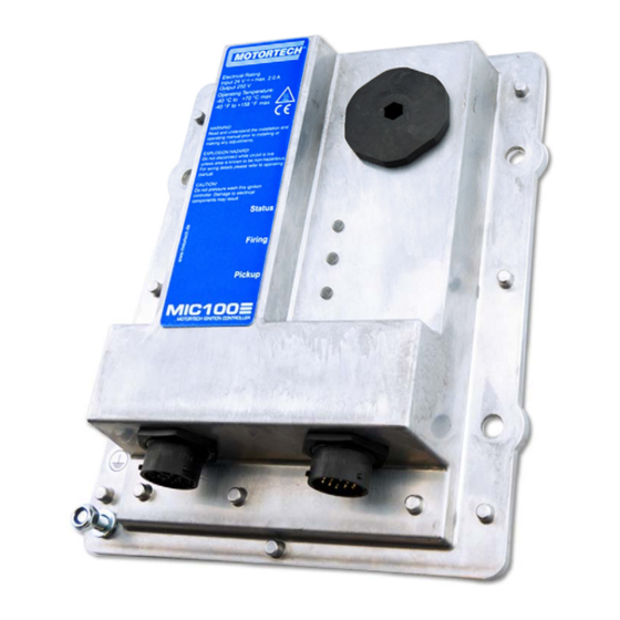
Page 24: Overview Drawings
The connectors shown correspond to the standard version. Other device versions may be equipped with different connectors. Service Interface Below the service screw is the service connection, which can connect the MIC100 to a computer. For this purpose the special MOTORTECH USB adaptor cable type1 must be used. Rev. 05/2020... -
Page 25: Led Functions
4 Product Description 4.1.9 LED Functions Labeling Function Status LED flashes green if the device is running with no errors. The LED flashes red if an error has occurred. For details, refer to the following overview. Firing LED lights up when the ignition is active. Pickup Flashing LED indicates activity of the pickups. - Page 26 4 Product Description Firing locked – 3 flashes green/off 250 ms, 750 ms off – Configuration/Wait for 0 RPM 6 flashes green/off 250 ms, 750 ms off The status LED flashes red: – Critical error/ Assertion fast flashing red/off 100 ms –...
- Page 27 4 Product Description The status LED flashes orange: Selftest – Flashing one time orange 250 ms on, 750 ms off Rev. 05/2020...
-
Page 28: Installation Instructions
Check the contents for completeness and verify that the device type meets your application requirements. Scope of Supply The scope of supply of the MIC100 ignition controller consists of the following components: – Ignition controller of the MIC100 series –... -
Page 29: Installation Of The Ignition Controller
5 Installation Instructions 5.2.1 Installation of the Ignition Controller Use the supplied installation material to mount the MIC100 on a suitable bracket. The hole patterns can be found in section Overview Drawings on page 24. Fasten the ignition controller to the selected installation location. -
Page 30: Determine The Installation Location Of The Pickup
5 Installation Instructions 5.3 Determine the Installation Location of the Pickup Set the position of the pickup depending on engine type and application. All angle reference information is based on: TDC 1st cylinder / compression cycle The installation location for the pickup must have adequate mechanical strength and must not exceed the specified temperature ranges. -
Page 31: Wiring Of The Device
6 Wiring of the Device 6.1 Input and Output Wiring on the Controller Operational safety! All connector screws and screw joints must be adequately tightened. Assignment of the wire colors Take the assignment of the wire colors of the wiring harness for the input and output wiring from the wiring diagram enclosed with the wiring harness. - Page 32 6 Wiring of the Device 19-Pole Connector for Input and Output Wiring (Standard Version) Assignment of the Connections Assignment Description Power supply L – Pickup Power Pickup Pickup Signal Pickup GND Pickup Shield Go/NoGo + Binary outputs Go/NoGo – ASO + ASO –...
-
Page 33: Input Wiring - Power Supply
6 Wiring of the Device 6.1.1 Input Wiring – Power Supply Operational safety! The proper functioning of the device is only guaranteed if the device is operated within the permissible supply voltage range. Therefore, use a power supply in accordance with the specifications in the operating manual. - Page 34 6 Wiring of the Device L ≙ 24 V DC (nominal voltage) Variations Battery Generator Control unit Power supply Battery Charger Rev. 05/2020...
-
Page 35: Input Wiring - Pickup
Example Configuration: 6+1 Trigger Disc, Active Pickup on the Camshaft The recommended distance to the triggering is 0.75 mm to 1 mm (0.03" to 0.04") for MOTORTECH pickups. Please note that additional fine-tuning is required for every pickup position due to the different conditions of the engines. -
Page 36: Input Wiring - Timing And Safety Devices
6.1.3 Input Wiring – Timing and Safety Devices Shared auxiliary supply voltage Devices of the MIC100 series do not have a separate auxiliary supply voltage for the analog current input. For devices requiring such a voltage, the auxiliary supply voltage of the pickup can also be used for the current input. - Page 37 6 Wiring of the Device See subsequent drawings for details X = bridge for permanent authorization (must be removed for external ignition authorization) Switch Start/Stop open Ignition – OFF closed Ignition – ON Two-Wire Transmitter Four-Wire Transmitter Rev. 05/2020...
- Page 38 6 Wiring of the Device Wiring MIC100 ignition controller and DetCon detonation control system The following diagram shows an example of the wiring of a MIC100 ignition controller with a DetCon detonation control system in cases where the analog current signal (4-20 mA) is to be used for the ignition timing adjustment.
-
Page 39: Output Wiring - Binary Outputs (Go/Nogo, Aso)
6 Wiring of the Device 6.1.4 Output Wiring – Binary Outputs (Go/NoGo, ASO) Example Configuration *) DetCon or other external device (for wiring of the DetCon, see following example) K1 = Go/NoGo relay L ≙ 24 V DC Binary output as low-side switch Binary output as high-side switch (L ≙... - Page 40 6 Wiring of the Device DetCon connection Connect the ASO output on the DetCon to the connections in A and in B on connector Synchronization. Rev. 05/2020...
-
Page 41: Output Wiring - Can Bus Interface
The product must be connected to a CAN bus as follows: First device Second-to-last device Second device Last device Information on protocols Please contact your MOTORTECH contact person if you require more information on the CANopen and J1939 protocols. ® Rev. 05/2020... - Page 42 6 Wiring of the Device CAN bus wiring Note the following when connecting the CAN bus: – Each bus end must be fitted with a terminating resistor of 120 Ω (see drawing). – The maximum wire length depends on the bit rate: Bit rate Maximum wire Maximum length...
-
Page 43: Ignition Coil Wiring
(see section Engine – Parameters on page 69). Conductor cross-section for primary wiring If you do not use a harness manufactured by MOTORTECH, the primary wiring must have a conductor cross-section of 1.5 mm². Rev. 05/2020... - Page 44 6 Wiring of the Device 12-Pole Output Connector Assignment of the Connections (Version with 8 Outputs) Pole Assignment Output 1 Output 2 Output 3 Output 4 Output 5 Output 6 Output 7 Output 8 Not assigned Not assigned Not assigned Ground For device versions with less ignition outputs, correspondingly less connections are assigned.
-
Page 45: Straight Order Wiring Of The Ignition Outputs
6.2.1 Straight Order Wiring of the Ignition Outputs Risk of damage to engine If you use MOTORTECH wiring rails for straight order wiring, it is absolutely necessary that they are correctly selected and installed for the respective engine. Even a rotated installation can cause serious damage to the engine, for example. -
Page 46: Straight Order Wiring Of The Ignition Outputs - Overview
6 Wiring of the Device 6.2.2 Straight Order Wiring of the Ignition Outputs – Overview The table contains the allocation of the MIC100 outputs to the cylinders. Version with 8 outputs Pole 8 outputs In-line engine V-engine Connector* Coil** Connector*... -
Page 47: Functions
– Inputs on page 77. 7.2 Monitoring of Pickup Signals The pickup signal is checked by the MIC100. Any other errors are displayed in the MICT. For more information on the errors, please refer to the overview in the section entitled Pickup Input Errors on page 108. -
Page 48: Ignition Timing Adjustment
7 Functions Use master control The outputs of the MIC100 are not SIL compliant. Therefore, always use an additional master control for safety-critical applications. 7.4 Ignition Timing Adjustment The ignition controller has several functions for the timing correction. Influences on ignition timing Be aware that the actual ignition timing of the engine can also be influenced by external signals (e. -
Page 49: Analog Current Input
7 Functions Base Timing Speed Curve Analog Current Input Ignition Timing Correction Limited by the min./max. Timing 7.4.1 Analog Current Input The timing point control can be adjusted with a linear current signal. This signal can be supplied, for example, by a potentiometer, a pressure sensor for charging pressure, or a detonation controller. - Page 50 7 Functions Configuration examples In this example the analog current input is configured in the Timing – Analog Inputs window as follows: – Lower Limit: 4 mA – Upper Limit: 20 mA Setting for the analog current input in the window Timing – Schedule A – General: –...
-
Page 51: Speed Curve
7.6 Output Monitoring Electronic switches are used for the ignition outputs of the MIC100 ignition controller If one of these switches is defective, this would lead to a primary short or a primary open output. This can cause problems when operating the engine or can damage the engine. -
Page 52: Access Control
MIC100. Although he has the full authorization set in the MICT, he is prompted to log in with the PIN for the Level 3 (Master) on the MIC100. A variety of functions are at your disposal in the four operating levels of the MIC100 . The figure below illustrates this: The following functions are available on the different levels: –... - Page 53 7 Functions – Level 2 (Service) Only the Service level has access to modifications of the runtime adjustments for Timing and Energy Limit and the commands Set Engine Hours, Set Spark Plug Hours. The self-test can also be carried out at this operating level. –...
-
Page 54: Settings Via The Mict
Internet at www.motortech.de. Installing the drivers Before you connect a computer with a MIC100 for the first time, it is necessary to install or update all necessary drivers. This driver installation is carried out via the MOTORTECH Driver Installer and it only needs to be... -
Page 55: Access Levels In The Mict
8.3 Access Levels in the MICT You can open the MICT on your computer via Start -> Programs -> MOTORTECH -> MICT 2.x.x -> MICT 2.x.x. After opening the MICT, select the access level for which you have clearance. The access level controls the options you have at your disposal in the MICT. -
Page 56: Configuration Pages (Overview)
8 Settings via the MICT – Service This level contains all functions for a standard installation. – Advanced Service This level offers full access to all functions of the MICT and is enabled and accessible for specially trained personnel only. The following sections describe the options at your disposal with the Advanced Service access level. -
Page 57: Menu Bar And Toolbar
– Indication of the access level of the user in the MICT – Indication of the operating level for the MIC100 if access control has been activated and the user has logged on with a PIN. – Indication of the MICT program version 8.5 Menu Bar and Toolbar... - Page 58 8 Settings via the MICT Symbol Menu Function Changes the MICT access level for accessing File -> Change Access Level the configuration data and functions. Prints the current configuration. File -> Print Prints the configuration to a PDF file. File -> Print To PDF File Opens a print preview of the configuration.
- Page 59 Acknowledge operational error not running. (Keyboard shortcut: Strg+R) The setup for the access control to the MIC100 Device -> Access Control is described in a separate section. Please read the section Access Control for MIC100 on page Opens the window Temperature Extremes in Device ->...
-
Page 60: Online Update Settings
Perform regular online updates MOTORTECH is constantly expanding its databases. Perform regular online updates to make optimal use of the opportunities that the MIC100 provides. The MICT uses data from an engine database and a coil database for the configuration. Such data can be updated with automatic online updates. -
Page 61: Self Test
8 Settings via the MICT 8.7 Self Test Operational safety! If you carry out a self test, it is essential for the gas supply to be switched off and no more residual gas is left in the combustion chamber. Non- compliance can result in damage to equipment or injury to persons. -
Page 62: Access Control For Mic100
– Control Start or stop a self test using the corresponding buttons. 8.8 Access Control for MIC100 If the access control to the MIC100 is activated, access to the following areas is possible with a PIN only: – Runtime Adjustment (Reset, timing and energy limit) –... -
Page 63: Login/Logout
8 Settings via the MICT To enable or disable the access control, proceed as follows: Open the input dialog via Device -> Access Control -> Enable or Disable access control. 2. Enter the PIN for the level Master (Level 3). 3. -
Page 64: Reset All Pins
In the menu bar, select the entry Device -> Access Control -> Get reset all PINs request key to open a window with the same name. 2. Send the request key with the serial number to your service contact person at MOTORTECH (refer to Customer Service Information on page 108). This key is valid only for the respective controller and only for a certain amount of time. -
Page 65: Create, Open, Save
8 Settings via the MICT 8.9.1 Create, Open, Save Click on the symbol to create a new configuration and select the corresponding device type. The device type corresponds to the first five digits of the arrangement number, which you can find on a label on your device. Click on the symbol to open a saved configuration. -
Page 66: Upload, Download
Click on the symbol to download the configuration set in the MICT to the MIC100. This function can only be executed while the ignition is not active. This action overwrites the existing configuration on the device. If applicable, the MICT first establishes a connection to the MIC100 connected. -
Page 67: Compatibility Information
MICT's configuration views. 8.9.3 Compatibility Information If you upload a configuration from the MIC100 to the MICT that does not correspond to the status of your MICT, or if you open this type of configuration in the MICT, the following situations may occur: –... -
Page 68: Configuration
8 Settings via the MICT 8.10 Configuration The window opens after you select the device type for a new configuration or an existing configuration or have uploaded one from the ignition controller. You can make changes to the configuration by selecting an entry from the navigation bar. The corresponding configuration data are then displayed in the configuration section and can be processed. -
Page 69: Engine - Parameters
8 Settings via the MICT 8.10.1 Engine – Parameters Engine Selection The MICT holds an engine database with data from various manufacturers and model series. Select the desired engine manufacturer, series, and type by clicking on the corresponding fields. Rev. 05/2020... - Page 70 You can use straight order wiring, if: – Wiring takes place via a corresponding MOTORTECH wiring harness and a MOTORTECH wiring rail. The harness is marked with the following information: PLEASE NOTE! The firing order needs to be configured directly in the ignition controller. The ignition coils on the wiring rail are marked with Connector Pin 1 to Connector Pin X.
- Page 71 8 Settings via the MICT Engine database MOTORTECH does not assume liability for the information in the engine database. Please contact MOTORTECH if discrepancies are found. New Engine Configuration Staff with the authorization for the Advanced Service level additionally has the option for entering the engine data manually, i.e., without selecting entries from the engine database.
-
Page 72: Engine - Ignition Outputs
8 Settings via the MICT 8.10.2 Engine – Ignition Outputs Make adjustments to the following settings as needed: – Number of Outputs Select the number of outputs for the respective output board. – Column: Output Select the number of the respective output. –... -
Page 73: Engine - Ignition Coils
8 Settings via the MICT Operational safety! Never connect more than one output to each ignition coil, as the output board can otherwise be damaged. The allocation of outputs on the output banks to contacts of the output connector of the device and the cylinders is determined by the wiring. -
Page 74: Engine - Speed Settings
Different coil types must not be mixed and also no equivalent or replacement types may be used. If a coil type used is not in the drop-down list, then the MIC100 is currently not used. -
Page 75: Engine - Pickups - General
Max. Power-on Speed Enter the maximum permitted start speed at which the MIC100 starts sending ignition pulses. A value of 6000 rpm is set as the default value: The MIC100 can be activated at the starter speed and immediately send ignition pulses. - Page 76 16 V. Shared auxiliary supply voltage Devices of the MIC100 series do not have a separate auxiliary supply voltage for the analog current input. For devices requiring such a voltage, the auxiliary supply voltage of the pickup can also be used for the current input.
-
Page 77: Engine - Pickups - Inputs
8 Settings via the MICT 8.10.6 Engine – Pickups – Inputs Type You can select the type of events that will occur on this input for each pickup input. Type and number of events are defined by the discs or ring gears used. If you decide not to use a pickup input, select the entry None from the list. - Page 78 8 Settings via the MICT Number of Events Enter the number of events that occur on the pickup if more than one event is expected. Enter the value for N and not the total number of events for the selected pickup type. The number of events depends on the selected pickup type.
- Page 79 8 Settings via the MICT Speed-dependent pre-trigger voltage For a passive pickup, the pre-trigger voltage is defined as follows: – Speed1: 150 RPM; Pre-trigger voltage1: 2 V – Speed2: 1000 RPM; Pre-trigger voltage2: 5 V The result is the following curve: Pre-trigger voltage Speed (RPM)
-
Page 80: Timing - Analog Inputs
8 Settings via the MICT 8.10.7 Timing – Analog Inputs Analog Inputs Base Settings The ignition timing can be adjusted via an analog current signal, which can be set within the limits of 0 mA to 20 mA. Set the Upper Limit and Lower Limit of the signals corresponding to your connected device. Also, you have the option to enter a Failure Threshold. -
Page 81: Timing - Schedule A - General
8 Settings via the MICT 8.10.8 Timing – Schedule A – General Limits Enter the limits of the timing point at which the ignition can fire. The timing points of the outputs will be limited to this range relative to the respective top dead center of the pertinent cylinder. The global timing can then not be shifted beyond this range by any adjustments. -
Page 82: Timing - Schedule A - Energy
8 Settings via the MICT Speed Curve The speed curve can be activated and disabled by mouse click and offsets the timing depending on the speed. A max. of eight speed points are available. If you select a number of points from the list, the corresponding number of fields is activated for input. -
Page 83: Miscellaneous - Communication
8 Settings via the MICT 8.10.10 Miscellaneous – Communication CAN1 Clicking on the checkbox CAN1 enables or disables the CAN interface on the device. – J1939/CANopen Select the desired protocol depending on the device you want to communicate with. For the ALL-IN-ONE gas communication use J1939. -
Page 84: Miscellaneous - Information
Setting the transfer rate Please note that all devices connected with a bus must be set to the same transfer rate. Information on protocols Please contact your MOTORTECH contact person if you require more information on the CANopen ® and J1939 protocols. -
Page 85: Runtime Data
8 Settings via the MICT Site and Module In this section, enter information on the system and the module for which the configuration will be used. Service Contact In this section, individual contact data can be saved that can be called up and displayed via MICT. -
Page 86: Runtime Data - Overview
8 Settings via the MICT 8.11.1 Runtime Data – Overview In this screen, you can find the following information: – Speed Indicator (analog) – Red pointer Displays the current registered speed – Yellow pointer Displays the maximum registered speed since last starting the engine –... - Page 87 8 Settings via the MICT – Operating Hours – Spark Plugs Indicates the current operating hours of the spark plugs – Engine Indication of current operating hours of the engine – Device State The status of the device is shown by the following status displays: Device status Description Idle...
-
Page 88: Runtime Data - Timing
Displays the misfire rate for all the ignition outputs for the past 32 cycles. – The number of misfires per second are calculated by the MIC100 as follows: 2-stroke engine: Number of currently misfiring outputs x RPM / 60 4-stroke engine: Number of currently misfiring outputs x RPM / 60 / 2 8.11.2 Runtime Data –... -
Page 89: Runtime Data - Bank A
8 Settings via the MICT 8.11.3 Runtime Data – Bank A In this screen, you can find the following information: – Column: Output Designation of the output – Column: Angle Current output firing angle – Column: Min. Spark Duration Minimum spark duration of the outputs –... -
Page 90: Runtime Data - States
8 Settings via the MICT – Columns: Misfire Status display for the different types of misfires (primary, open, short circuit). In case of misfire, the respective status display turns red, otherwise it is gray. With a yellow status display misfires have occurred since the last reset of the counter. If you hold the pointer over the status display, an overview of the misfire counter of the respective output is displayed for all types of misfires. -
Page 91: Runtime Data - Diagnostics
8 Settings via the MICT 8.11.6 Runtime Data – Diagnostics In this screen, you can find the following information: – CAN State The status display indicates the current error handling status of the device for the CAN bus communication: – Error Active The device is in normal status of the bus communication. -
Page 92: Runtime Data - Temperatures
8 Settings via the MICT – Controller Board – Supply Voltage Current voltage supply of the controller board. – Pickup Input 1 Pre-Trigger Voltage Current pre-trigger voltage for the pickup inputs (refer to Engine – Pickups – Inputs on page 77). During operation the pre-trigger voltage for passive pickups is increased depending on the speed, so that the ignition controller is less prone to interferences. -
Page 93: Runtime Data - Information
In this view, you can find an overview of the device and version data. If problems arise, you can print the current runtime data and send them to the MOTORTECH Service Department by fax or as a PDF file by email. For fast support, we will then immediately have all required information. -
Page 94: Log
If the function is active, the view panel focuses on the latest message. – Log level The selection of the log level is specified by MOTORTECH if needed. – Write log to file This checkbox activates or deactivates, respectively, the saving of the logged data in a selected file. -
Page 95: Runtime Adjustments
8 Settings via the MICT 4. Select the level specified by MOTORTECH from the list Log level. 5. Leave the window open. ▸ The log messages are logged both in the window and in the selected file. 8.13 Runtime Adjustments Click on the symbol to open the window Runtime Adjustments. -
Page 96: Runtime Adjustments - Timing
8 Settings via the MICT 8.13.2 Runtime Adjustments – Timing The global ignition timing position can be corrected by 50 °crankshaft (advanced/retarded) while the device is being operated. The correction is made with the buttons: – 0.1 ADV/RET in 0.1° increments to advance or retard –... -
Page 97: Schedule Curve
8 Settings via the MICT 8.14 Schedule Curve Click on the symbol to open the window Schedule. 8.14.1 Schedule Curve – Simulation The schedule curve visualizes the configurations of the schedule and simulates the influence of the analog current input over the speed range. Changes made by turning the control button or entering the desired value are displayed simultaneously. -
Page 98: Schedule Curve - Runtime Values
8 Settings via the MICT – Timing Point Displays the global ignition timing as it changes during the simulation. While connected to the device, the ignition timing is simulated depending on the actual engine speed and marked as in the diagram. 8.14.2 Schedule Curve –... -
Page 99: Coils
Timing Point Displays the current global ignition timing. 8.15 Coils The MICT has a database with technical information on MOTORTECH ignition coils. Open the database as follows: Tools -> Coils You have the option of storing and printing information on the ignition coils present in the database. -
Page 100: General
8 Settings via the MICT 8.15.1 General Details The following information is provided: – Name Coil name – Coil Type ID Used to clearly identify the ignition coil – Data Version Shows data version of the ignition coil selected in the database. The data version of the ignition coil configured in the ignition controller is displayed in the runtime data in the view Information (refer to Runtime Data –... - Page 101 8 Settings via the MICT Coil Parameters The following information is provided: – Energy Limit [mJ] Displays the permitted value range for the energy limit in mJ. The energy limit is configured in the view Timing – Schedule A – Energy (refer to Timing – Schedule A – Energy on page 82). Rev.
-
Page 102: Operation
The ignition controller is shut down by disconnecting it from the power supply. 9.3 Firmware Update Using the MOTORTECH Flash Tool, you can update the firmware of the ignition controller. The program is included on the storage device enclosed with USB adaptor cable type1. The adaptor cable is necessary to connect the device to a computer. - Page 103 Follow the instructions of the installation routine. Note that the license agreement terms must be accepted before using the MOTORTECH Flash Tool. ▸ The MOTORTECH Flash Tool is set up. You can now connect your computer to the ignition controller via the USB interface. Rev. 05/2020...
- Page 104 9 Operation Menu Bar and Toolbar After launching the MOTORTECH Flash Tool, the following functions are available to you via the icons on the toolbar and the entries in the menu bar: Symbol Menu Function Opens a firmware file. File -> Open Exits the program.
- Page 105 3. In the Status section under Device, check if your device has been recognized properly. ▸ If the MOTORTECH Flash Tool was unable to detect a device even though it is connected to your computer via the USB interface and the USB drivers have been installed correctly, you can usually still update the firmware.
- Page 106 9 Operation Help with connection problems If a correctly connected device is not found during the automatic search, this can, for example, be because too many communication interfaces are assigned and must be checked. In this case, an interface from the drop- down list Port in the area Connection can be selected and thus specified.
-
Page 107: Errors
10 Errors 10.1 Possible Faults The MIC100 ignition controllers include several safety functions that can shut down the engine in case of fault: – Overspeed protection – External shut-down contact (Start/Stop) – Misfire detection (primary) – Internal failure of the high voltage supply –... -
Page 108: Misfire Detection (Primary)
Acknowledgement of the error via CAN-Bus 10.3 Customer Service Information You can reach our customer service during business hours at the following phone and fax number, or by email: Phone: +49 5141 93 99 0 Fax: +49 5141 93 99 99 Email: service@motortech.de Rev. 05/2020... -
Page 109: Returning Equipment For Repair/Inspection
Send the device and the return form to one of the two addresses below or to the nearest MOTORTECH representative: MOTORTECH GmbH MOTORTECH Americas, LLC Hogrevestr. 21-23 1400 Dealers Avenue, Suite A 29223 Celle... -
Page 110: Maintenance
Service the spark plugs as per the instructions of the spark plug and engine manufacturers. 11.2 Spare Parts and Accessories For spare parts and accessories for MIC100 ignition systems, please refer to our current product guide, which is available for download on the Internet at www.motortech.de. -
Page 111: Index
12 Index A Device (continued) Select type ..........65 Abbreviation ..........8 Start-up ........... 102 Access Control Switching off ........... 102 Activate ............. 62 Downgrade Device ............62 Process sequence ........102 Overview ........... 52 Advanced service E Access level ..........55 Electrostatics .......... - Page 112 R Overview ..........89 Read only MOTORTECH Access level ..........55 Address ........... 109 Repair ............109 MOTORTECH Integrated Configuration Tool Required current ........... 21 Access level ..........55 Return shipment .......... 109 Design ............56 S Installation ..........54 Safety instructions ........
- Page 113 12 Index Shut off ............102 W Software Wiring Access level ..........55 Auxiliary synchronization output ....39 Design ............56 CAN bus ............ 41 Installation ..........54 Direct ..........45, 69 Menu overview .......... 57 Go/NoGo output ........39 Operation ..........
Need help?
Do you have a question about the MIC100 and is the answer not in the manual?
Questions and answers