
Related Manuals for Motortech ITB 50 Series


Summary of Contents for Motortech ITB 50 Series
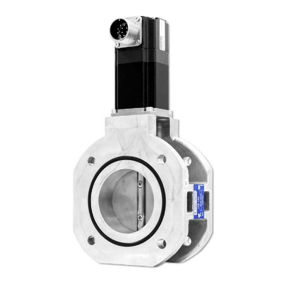
- Page 1 ITB – Throttle with Integrated Stepper Motor P/N 30.43. xxx Assembly Instructions P/N 01.50.034 | Rev. 06/2022...
- Page 2 MOTORTECH products and the MOTORTECH logo are registered and/or common law trademarks of the MOTORTECH GmbH. All further trademarks and logos displayed or used in this publication are the property of the respective entitled person and are used for reference purposes only.
-
Page 3: Table Of Contents
Table of Contents 1 General Information ..................... 4 1.1 What Is the Purpose of these Assembly Instructions? ..........4 1.2 Who Are these Assembly Instructions Targeted to? ............ 4 1.3 What Symbols Are Used in the Assembly Instructions? ..........4 ... -
Page 4: General Information
1 General Information Prior to use, read these assembly instructions carefully and familiarize yourself with the product. Installation and start-up should not be carried out before reading and understanding this document. Keep these assembly instructions readily available so that you can reference them as needed. -
Page 5: Which Abbreviations/Acronyms Are Used In The Operating Manual
Integrated Throttle Throttle with Body integrated stepper motor MICT MOTORTECH Configuration software for Integrated MOTORTECH control units Configuration Tool Universal Serial Bus Serial connection system to link a computer to external devices Rev. 06/2022... -
Page 6: Safety Instructions
Risk of burning! The surfaces of the system may heat up to high temperatures. 2.1 Proper Disposal For the proper disposal of MOTORTECH devices, observe the information provided at www.motortech.de . Rev. 06/2022... -
Page 7: Intended Use
3 Intended Use 3.1 Functional Description The ITB throttle controls the supply of the gas-/air mixture to the gas engine. The integrated stepper motor evaluates signals from a VariStep stepper motor driver and implements them in changing the opening of the throttle. The speed and power of the engine are regulated in this way. -
Page 8: Applications
3 Intended Use 3.2 Applications The ITB throttles are suitable for use on stationary gas engines. Series with different valve diameters are available for different gases and performance classes. A high temperature version (HT) can be used for operation in front of the intercooler. These permit a temperature of the medium flowing through of up to +200 °C (+392 °F). -
Page 9: Product Description
4 Product Description 4.1 Technical Data The throttles have the following technical properties: Feature Value Dimensions See chapter Overview Drawings on page 12 Weight See following table. Shape of device See chapter Overview Drawings on page 12 80° Maximum rotation angle of the throttle body Chemical resistance Water, oil, gaseous fuels... -
Page 10: Warning Notices On The Device
4 Product Description Series Diameter of the throttle body Type Weight 150 series 90 mm (3.54") Standard 7.0 kg (15.43 lbs) 90 mm (3.54") 7.2 kg (15.87 lbs) 100 mm (3.94") Standard 6.8 kg (14.99 lbs) 100 mm (3.94") 6.9 kg (15.21 lbs) 200 series 100 mm (3.94") Standard... -
Page 11: Product Identification - Labeling On The Device
4 Product Description 4.3 Product Identification – Labeling on the Device The necessary numbers for unique product identification are on the device: Nameplate ITB on the Throttle Body Abb. Meaning ITB part number ITB serial number Stepper Motor Nameplate Abb. Meaning Part number of the stepper motor Production code... -
Page 12: Digression: Control Of The Stepper Motor
4 Product Description 4.4 Digression: Control of the Stepper Motor In the standard application, the stepper motor of the throttle is driven by the VariStep stepper motor driver. For example, if you want to implement a direct activation from a master control, you receive the technical details for activation of the stepper motor in the following section. -
Page 13: Series
4 Product Description 4.5.1 50 Series Standard diameter of the throttle (D): 42 mm (1.65") possible diameters of the throttle: 41 mm (1.61") to 44 mm (1.73") P/N 30.43.055-D and P/N 30.43.055-D-HT also correspond to the following drawings, but without the gasket (O-ring, 56.75 mm x 3.53 mm [2.23"... - Page 14 4 Product Description HT versions (P/N 30.43.050-D- HT) Rev. 06/2022...
-
Page 15: 100 Series
4 Product Description 4.5.2 100 Series Standard diameters of the throttle (D): 60 mm (2.36"), 68 mm (2.68") possible diameters of the throttle: 48 mm (1.89") to 68 mm (2.68") P/N 30.43.105-D and P/N 30.43.105-D-HT also correspond to the following drawings, but without the gasket (O-ring, 82.14 mm x 3.53 mm [3.23"x 0.14"]) and the groove required for it. - Page 16 4 Product Description HT version Rev. 06/2022...
-
Page 17: 140 Series
4 Product Description 4.5.3 140 Series Standard diameters of the throttle (D): 75 mm (2.95"), 80 mm (3.15"), 85 mm (3.35") possible diameters of the throttle: 73 mm (2.8) to 85 mm (3.35") P/N 30.43.145-D and P/N 30.43.145-D-HT also correspond to the following drawings, but without the gasket (O-ring, 98.02 mm x 3.53 mm [3.86"x 0.14"]) and the groove required for it. - Page 18 4 Product Description HT version Rev. 06/2022...
-
Page 19: 150 Series
4 Product Description 4.5.4 150 Series Standard diameters of the throttle (D): 90 mm (3.54"), 100 mm (3.94") possible diameters of the throttle: 82 mm (3.23") to 104 mm (4.09") P/N 30.43.155-D and P/N 30.43.155-D-HT also correspond to the following drawings, but without the gasket (O-ring, 116 mm x 3 mm [4.57"x 0.12"]) and the groove required for it. - Page 20 4 Product Description HT version Rev. 06/2022...
-
Page 21: 200 Series
4 Product Description 4.5.5 200 Series Standard diameters of the throttle (D): 100 mm (3.94"), 105 mm (4.13"), 110 mm (4.33"), 115 mm (4.53"), 120 mm (4.72"), 125 mm (4.92") possible diameters of the throttle: 98 mm (3.86") to 125 mm (4.92") P/N 30.43.205-D and P/N 30.43.205-D-HT also correspond to the following drawings, but without the gasket (O-ring, 148.82 mm x 3.53 mm [5.86"... - Page 22 4 Product Description HT versions (P/N 30.43.200-D- HT) Rev. 06/2022...
-
Page 23: Wiring Of The Device
5 Wiring of the Device 5.1 Connector Stepper Motor / Encoder The connection of the stepper motor to the VariStep stepper motor driver is carried out using the original MOTORTECH harness via the 10-pin connector on the stepper motor: Description Stepper motor phase A1... -
Page 24: Assembly Instructions
6 Assembly Instructions 6.1 Unpacking Unpack the device taking care not to damage it, and ensure that the assembly instructions are always stored with the device and are easily accessible. Check the contents for completeness and verify that the device type meets your application requirements. Scope of Supply The scope of supply of the device consists of the following components: –... - Page 25 6 Assembly Instructions Example: 140 series 2. Use four through bolts or threaded rods (strength class 8.8 or higher) to mount the butterfly valve between the two flanges. Depending on the thread used, observe the following tightening torques (for strength class 8.8): –...
-
Page 26: Connecting The Device
6 Assembly Instructions 6.3 Connecting the Device Risk of destruction! Please observe the following procedure when connecting the stepper motor to the VariStep stepper motor driver: Configure the VariStep stepper motor driver for the desired ITB throttle (see section External device in the operating manual for the VariStep stepper motor driver). -
Page 27: Errors
Check the configuration via the MICT. Observe the error messages displayed. For this, also read the corresponding sections in the operating manual on the VariStep stepper motor driver. Cause 3: The stepper motor is defective. Solution 3: The ITB throttle has to be replaced. Please contact your MOTORTECH contact person. Rev. 06/2022... -
Page 28: Maintenance
8.2 Returning Equipment for Repair / Inspection To return the device for repair and inspection, obtain a return form from your MOTORTECH contact person (see Customer Service Information on page 28). After you have completely filled out the return form and returned it to MOTORTECH, MOTORTECH will send you back the return form and a delivery note with RMA number specified. - Page 29 Rev. 06/2022...
Need help?
Do you have a question about the ITB 50 Series and is the answer not in the manual?
Questions and answers