Table of Contents
Advertisement
Quick Links
Installation and Maintenance
Instruction Manual
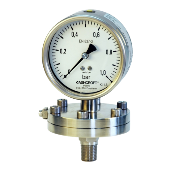
Diaphragm pressure gauge, model P5500 and P6500
for explosion risk areas pursuant to Directive 2014/34/EU (ATEX)
In the following configuration:
• ###P5500/P6500###ATEX diaphragm pressure gauge without switching contact
• ###P5500/P6500###I####ATEX diaphragm pressure gauge with inductive proximity switches
IM-P5500/ATEX-E-Rev C
05/2020
Page 1 of 28
P/N 095I102-02EN
Advertisement
Table of Contents

Related Manuals for Ashcroft P5500


Summary of Contents for Ashcroft P5500
- Page 1 Diaphragm pressure gauge, model P5500 and P6500 for explosion risk areas pursuant to Directive 2014/34/EU (ATEX) In the following configuration: • ###P5500/P6500###ATEX diaphragm pressure gauge without switching contact • ###P5500/P6500###I####ATEX diaphragm pressure gauge with inductive proximity switches IM-P5500/ATEX-E-Rev C 05/2020 Page 1 of 28...
-
Page 2: Table Of Contents
Environmental protection............................. 5 Use in explosion risk areas pursuant to Directive 2014/34/EU (ATEX) ..............6 P5500/P6500 without switching contact ......................6 P5500/P6500 I#### with inductive proximity switches SJ2-N ................6 Technical data ................................7 Labeling on the device ..............................8 Labeling on the device for explosion risk areas (ATEX) .................. - Page 3 Appendix ................................13 12.1 Declaration of conformity model P5500......................13 12.2 Declaration of conformity model P5500 with inductive switches ..............15 12.3 EU design type test certification for inductive proximity switches of types SJ2-N ........17 12.4 Data sheet for diaphragm pressure gauge P5500/P6500 ................28...
-
Page 4: General Remarks
For the product described here, we offer a warranty pursuant to Section 6 Guarantee in Respect of Defects in our General Terms and Conditions of Delivery and Payment. 1.6 Manufacturer’s address, customer services Ashcroft Instruments GmbH Tel.: +49 (0) 2401/808-888 Fax.:... -
Page 5: Staff Qualifications (Target Group Assessment)
Safety instructions for proper operation of the device must be respected. They are to be provided by the operator for use by the respective personnel for installation, servicing, inspection and operation. Risks from electrical energy and from the released energy of the medium, from escaping media and from improper connection of the device must be eliminated. -
Page 6: Use In Explosion Risk Areas Pursuant To Directive 2014/34/Eu (Atex)
The documentation has been filed with TÜV-Nord-Cert NB 0044 (see declaration of conformity). Labeling: 3.2 P5500/P6500 I#### with inductive proximity switches SJ2-N Area of use: Explosion risk areas Zone 1 and 2, and 21 and 22, risk from gases and dry dust. -
Page 7: Technical Data
Warning! With gaseous media, the device temperature may increase due to compression heat. In such cases, the rate of the pressure change must be regulated or the permitted temperature of the measuring medium reduced. Note: For a change in differential pressure between 10 % and 90 % of the measuring range and a pulse frequency of < 0.06 Hz, the temperature increase is <10 K. -
Page 8: Labeling On The Device
5.1 Labeling on the device for explosion risk areas (ATEX) The label with the marking for explosion risk areas is located on the outside of the housing. Device without switching contacts: ###P5500####ATEX Device with integrated inductive proximity switch: ###P5500#### I####ATEX 6 Construction and function 6.1 Overview Diaphragm Movement 6.2 Description of function... -
Page 9: Description Of Components
6.3.4 Rear wall/plug with blow-out capability The pressure gauge has a plug capable of blowing out on the rear wall of the housing (Model P5500) or a rear wall capable of blowing out (Model P6500). These act as a safety feature pursuant to EN 837-3 and simultaneously allow for temperature compensation for the housing, via a rubber membrane. -
Page 10: Mounting/Installation
The installation location should be chosen such that the work-spaces for operating personnel are not located to the rear of the pressure gauge. 8.3 Mounting/Installation 8.3.1 Process connection As standard, the device is equipped for pipework mounting with a pressure connection shank pursuant to DIN EN 837- 3. -
Page 11: Subsequent Relocation Of The Gauge (By The Customer)
Depressurize the pressure metering pipe. Open the vent valve as shown in the diagram, and carefully remove the entire valve bushing from the housing. Adjust the indicator arm using the zero point adjustment screw to the zero point on the scale. Refit the valve bushing in the housing. -
Page 12: Cleaning And Maintenance
Check of electrical connections. 9.3 Cleaning and maintenance Cleaning is carried out using a non-aggressive cleaning agent, with the ventilation valve closed and respecting the protection category of the device. 10 Faults 10.1 Safety Defective or faulty pressure gauges put the operational safety and process safety of the plant at risk, and can lead to a risk or injury to persons, the environment or the plant. -
Page 13: Appendix
12 Appendix 12.1 Declaration of conformity model P5500 Page 13 of 28... - Page 14 Page 14 of 28...
-
Page 15: Declaration Of Conformity Model P5500 With Inductive Switches
12.2 Declaration of conformity model P5500 with inductive switches Page 15 of 28... - Page 16 Page 16 of 28...
-
Page 17: Eu Design Type Test Certification For Inductive Proximity Switches Of Types Sj2-N
12.3 EU design type test certification for inductive proximity switches of types SJ2-N Page 17 of 28... - Page 18 Page 18 of 28...
- Page 19 Page 19 of 28...
- Page 20 Page 20 of 28...
- Page 21 Page 21 of 28...
- Page 22 Page 22 of 28...
- Page 23 Page 23 of 28...
- Page 24 Page 24 of 28...
- Page 25 Page 25 of 28...
- Page 26 Page 26 of 28...
- Page 27 Page 27 of 28...
-
Page 28: Data Sheet For Diaphragm Pressure Gauge P5500/P6500
12.4 Data sheet for diaphragm pressure gauge P5500/P6500 Detailed data sheet is available from suppliers website (see 1.6 Manufacturer’s address, customer services) This Table refers to specific documents: Model Description Document P5500 Diaphragm type pressure gauge model P5500 G1.P5500 P6500 Solid front diaphragm type pressure gauge model P6500 G1.P5500...
Need help?
Do you have a question about the P5500 and is the answer not in the manual?
Questions and answers