Table of Contents
Advertisement
Advertisement
Table of Contents

Related Manuals for Ashcroft 2032


Summary of Contents for Ashcroft 2032
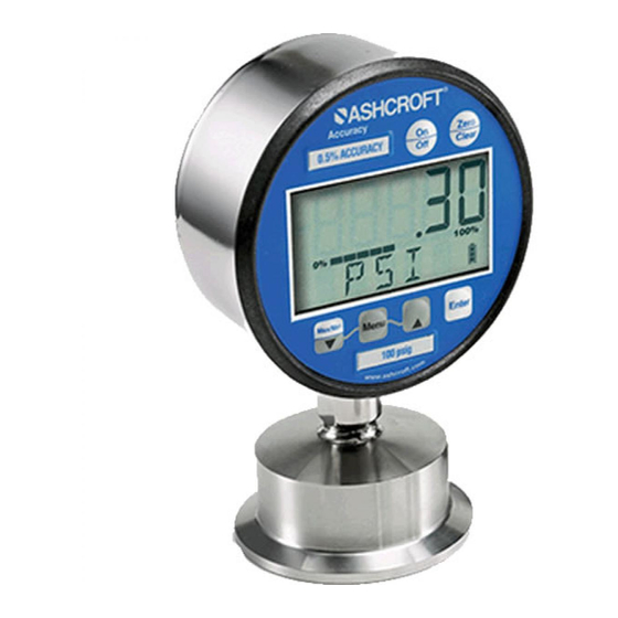
- Page 1 Digital Sanitary Gauge Operating Instructions I&M008-10162-10/08...
- Page 2 Optional 4-20mA output, switching and line- power add to the versatility of the gauge. With the range printed on the keypad, Ashcroft digital gauges meet ASME B40.7 specification. See a complete listing of product features and specifications on pages 16.
-
Page 3: Table Of Contents
TABLE OF CONTENTS Quick Reference ..........4-5 Keypad Functions ..........6-8 • ON/OFF KEY • ZERO/CLEAR KEY • MIN/MAX KEY (down arrow key) • MENU KEY • BACKLITE KEY (up arrow key) • ENTER KEY MENU Functions (MENU Mode) ........8-15 • Engineering Units •... -
Page 4: Quick Reference
QUICK RE .88˝ high digital display (4 ⁄ ˝ case) .60 high digital display(3˝ case) Bar graph % of full scale Flashing display when unit pressured below zero Press to indicate minimum or maximum pressure gauge has measured Press again to return to pressure units 316LSS Press to read menu... - Page 5 FERENCE Press to turn unit on or off While in unit of measurement mode (eg: psi), press the ZERO CLEAR button to rezero the gauge. This feature functions when displayed pressure is within ±5% or 10% of zero value Flashing display when unit pressurized beyond full-scale This bar graph indicates battery level;...
-
Page 6: Keypad Functions
KEYPAD FUNCTIONS Turns the gauge on and off. When pressing the ON/OFF key while in the off position, gauge start- ON/OFF up display first indicates the software version followed by the model number and gauge pres- sure range. The gauge will then display indicated pressure and be ready for use. -
Page 7: (Down Arrow Key)
KEYPAD FUNCTIONS This key allows for customization of the gauge. Pressing the MENU key allows cycling through MENU the main MENU items; UNITS, CONFIG, GRAPH, OFF, UPDAT & DAMP. Any item changed in the Menu become the new default setting(s). Revised settings are saved in the event of power loss. - Page 8 KEYPAD FUNCTIONS This key allows for selecting gauge features in the menu finalizing selection. Use of the enter key is ENTER described throughout operating instructions. MENU OPTIONS UNITS: 12 units of measurement are available: psi, mmHG, O with three temperature options: 20°C, 60°F, 4°C*, mBar, inHg, ftH O, mPa, kPa, kg/cm and bar.
-
Page 9: Menu Functions (Menu Mode)
KEYPAD FUNCTIONS MENU FUNCTIONS How to Use Your Menu Functions To set a user password (SETPW): Step 1: Press the Menu key on the keypad Step 2: Press the (up arrow key) or (down arrow key) until the word CONFIG appears. Step 3: Press Enter. - Page 10 MENU FUNCTIONS To use RECAL option: Step 1: Press the Menu key on the keypad Step 2: Press the (up arrow key) or (down arrow key) on the keypad until the word CONFIG appears. Step 3: Press Enter. Step 4: Enter user password if it has been programmed. Step 5: Press (up arrow key) or (down arrow key)
- Page 11 MENU FUNCTIONS Note: Calibration of Zero, mid-scale or span can be set inde- pendently of each other. For instance, if only full-scale cali- bration is required, press the (down arrow key) until the gauge display indicates full-scale pressure. Press Enter and proceed as indicated above.
- Page 12 MENU FUNCTIONS Step 3: press ENTER. The current setting (ENAB or dISAB) will be displayed. Step 4: Press the (up arrow key) or (down arrow key) on the keypad to select a setting. Step 5: Press ENTER To finalize the setting. GRAPH: This option allows the user to change the BAR graph on the gauge display to correspond to any desired pressure within the pressure limits of the gauge.
- Page 13 MENU FUNCTIONS Step 5: Press the ENTER key to finalize your choice. The gauge display will now display SET. After two seconds the screen will display the pressure value for 0% on the top line. The middle line indicates the bar graph at 100% of fullscale.
- Page 14 MENU FUNCTIONS Step 2: Press the (up arrow key) or (down arrow key) until the word UPDATE appears. Step 3: Press Enter. Step 4: Press the (up arrow key) or (down arrow key) to select an update rate. Step 5: Press ENTER to finalize the selection. DAMP or dampening: with five different options, this mode allows for taking process pressure readings and averaging them.
- Page 15 MENU FUNCTIONS Note: Setpoints are limited to the full-scale pressure range of the gauge. Step 4: Press the (up arrow key) or (down arrow key) on the keypad to increase or decrease switch set-point Step 5: Press the ENTER key to finalize switch setpoint. The gauge will display SET.
-
Page 16: Engineering Units
DIGITAL SANITARY GAUGE SPECIFICATIONS Type Conventional Tri-clamp: 2032 (battery), 2132 (4-20mA), 2232 (line) In-line Tri-clamp: 2036 (battery), 2136 (4-20mA), 2232 (line) Accuracy: Terminal Point Full Scale .25% F.S. Accuracy: Case Size 3˝ Case Material/Finish (3˝) 300 series SS, Electropolished Case Enclosure Rating... -
Page 17: Display Messages
DIGITAL SANITARY GAUGE RANGES: Comp. mmHg in.Hg Bar/ (psi) (press.) (press.) mBar -15/0/15 1500 -15/0/30 2000 1000 -15/0/60 3000 30 -15/0/100 1000 1000 1500 1600 2000 1000 2500 1000 1000 2500 4000 1600 4000 6000 2000 5000 8000 1000 3000 1500 6000 2000... -
Page 18: Wiring Diagrams
WIRING DIAGRAM POWER SUPPLY – PIN A GAUGE (–) PIN B V– – METER 4-20mA (seperate power supply required when switch(s) is/are ordered) Load Limitations 4-20mA Output Only 1000 OPERATING REGION Loop Supply Voltage (Vdc) Vdc MIN = 12V + [0.022A* X (RL) ] = Loop Resistance (ohms) = Sense Resistance (ohms) = Wiring Resistance (ohms) - Page 19 – 19 –...
- Page 20 PANEL Battery Installation and Replacement: The Types 2032 & 2036 comes standard with batteries installed. These gauges use qty (2) AA alkaline batteries. Use alkaline, non-rechargeable batteries only. Batteries have a life of approximately 1500 hours. Battery life is dependent on gauge usage, backlite settings and power off settings.
Need help?
Do you have a question about the 2032 and is the answer not in the manual?
Questions and answers