Table of Contents
Troubleshooting

Related Manuals for NEC PA803UL


Summary of Contents for NEC PA803UL
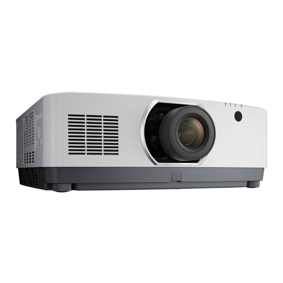
- Page 1 Projector PA803UL/PA703UL/PA653UL User’s Manual Please visit our web site for User’s Manual in the latest version: https://www.nec-display.com/dl/en/pj_manual/lineup.html Model No. NP-PA803UL/NP-PA703UL/NP-PA653UL...
- Page 2 (3) Great care has been taken in the preparation of this user’s manual; however, should you notice any questionable points, errors or omissions, please contact us. (4) Notwithstanding article (3), NEC will not be responsible for any claims on loss of profit or other matters deemed to result from using the Projector.
- Page 3 AC 120 V : North America Safety Cautions Precautions Please read this manual carefully before using your NEC projector and keep the manual handy for future reference. CAUTION To turn off main power, be sure to remove the plug from power outlet.
- Page 4 Important Information Disposing of your used product In the European Union EU-wide legislation as implemented in each Member State requires that used electrical and electronic prod- ucts carrying the mark (left) must be disposed of separately from normal household waste. This includes projectors and their electrical accessories.
- Page 5 Important Information Important Safeguards These safety instructions are to ensure the long life of your projector and to prevent fire and shock. Please read them carefully and heed all warnings. Installation • Do not place the projector in the following conditions: - on an unstable cart, stand, or table.
- Page 6 Important Information Fire and Shock Precautions • Ensure that there is sufficient ventilation and that vents are unobstructed to prevent the build-up of heat inside your projector. Allow enough space between your projector and a wall. (→ page xi) • Prevent foreign objects such as paper clips and bits of paper from falling into your projector. Do not attempt to retrieve any objects that might fall into your projector.
- Page 7 Important Information • Do not use the malfunctioned projector. It may cause of not only electric shock or fire but also serious damage to your eye sight. • Do not let children to operate the projector by themselves. If the projector is operated by children, adults need to attend and keep their eyes on children.
- Page 8 Obey the laws and regulations of your country in relation to the installation and management of the device. • Outline of laser emitted from the built-in light module: • Wave length: 455 nm • Maximum power: 140 W (PA703UL/PA653UL), 168 W (PA803UL) • Radiation pattern from the protective housing: • Wave length: 455 nm •...
- Page 9 Important Information Laser light radiation range The figure below shows the maximum radiation range of the laser light. Horizontal angle (unit: degree) Right Lens position Center Lens unit Zoom Right most (Reference Left most value) Tele 31.7 23.8 31.7 NP40ZL Wide 41.0 31.9...
- Page 10 Important Information • The caution and the explanatory labels of the LASER PRODUCT in CLASS 3R conforming to IEC 60825-1 Second edition, and in Class 1 conforming to IEC 60825-1 Third edition are stuck on the below indicated positions. For USA Label 1 Label 2 Label 1...
- Page 11 • The Federal Communications Commission does not allow any modifications or changes to the unit EXCEPT those specified by NEC Display Solutions of America, Inc. in this manual. Failure to comply with this government regulation could void your right to operate this equipment.
- Page 12 Important Information About Copyright of original projected pictures: Please note that using this projector for the purpose of commercial gain or the attraction of public attention in a venue such as a coffee shop or hotel and employing compression or expansion of the screen image with the following func- tions may raise concern about the infringement of copyrights which are protected by copyright law.
- Page 13 Important Information Clearance for Installing the Projector Allow ample clearance between the projector and its surroundings as shown below. The high temperature exhaust coming out of the device may be sucked into the device again. Required clearance is same whenever the projector is installed in any angle.
-
Page 14: Table Of Contents
Table of Contents Important Information .................... i 1. Introduction ......................1 ❶ What’s in the Box? ......................1 ❷ Introduction to the Projector ....................2 General ........................2 Light source · Brightness ..................2 Installation .........................2 Videos ........................2 Network ........................3 Energy-saving ......................3 About this user’s manual ...................4 ❸... - Page 15 Table of Contents 3. Convenient Features ..................30 ❶ Turn off the light of the projector (LENS SHUTTER) .............30 ❷ Turning off the Image and Sound ..................30 ❸ Shift the On-Screen Menu displaying position ..............31 ❹ Freezing a Picture ......................32 ❺ Enlarging a Picture .......................32 ❻...
- Page 16 Table of Contents 5. Using On-Screen Menu ................. 74 ❶ Using the Menus ......................74 ❷ Menu Elements ......................75 ❸ List of Menu Items ......................76 ❹ Menu Descriptions & Functions [INPUT] ..............82 ❺ Menu Descriptions & Functions [ADJUST] ..............86 [PICTURE] ......................86 [IMAGE OPTIONS] ....................90 [VIDEO] ........................94 [3D SETTINGS] ......................96...
- Page 17 Table of Contents 6. Connecting to Other Equipment ............138 ❶ Mounting a lens (sold separately) ................138 Mounting the lens....................138 Removing the lens ....................140 ❷ Making Connections ....................141 Analog RGB signal connection ................141 Digital RGB signal connection ................142 Connecting Component Input ................144 Connecting HDMI Input ..................145 Connecting to a HDBaseT transmission device (sold commercially) ....146 Connecting several projectors ................147...
-
Page 18: Introduction
(→ page 139) For North America only Limited warranty For customers in Europe: You will find our current valid Guarantee Policy • Important Infomation NEC Projector CD-ROM on our Web Site: (7N8N7993) User’s manual (PDF) www.nec-display-solutions.com • Quick Setup Guide (For North... -
Page 19: ❷ Introduction To The Projector
This section introduces you to your new projector and describes the features and controls. General • Liquid crystal type high brightness/high resolution projector Model Brightness Resolution Aspect Ratio PA803UL 8000 lm WUXGA (1920 × 1200) 16:10 PA703UL 7000 lm WUXGA (1920 × 1200) 16:10... -
Page 20: Network
LAN connection. Moreover, it has function to send an image to the projector and register it as the logo data. Please visit our web site for downloading each software. URL: https://www.nec-display.com/dl/en/index.html Energy-saving • Energy-saving design with a standby power consumption of 0.15 W (100-130 V AC) / 0.21 W (200-240 V AC) When the on-screen menu’s standby mode is set to “NORMAL”... -
Page 21: About This User's Manual
1. Introduction About this user’s manual The fastest way to get started is to take your time and do everything right the first time. Take a few minutes now to review the user’s manual. This may save you time later on. At the beginning of each section of the manual you’ll find an overview. -
Page 22: ❸ Part Names Of The Projector
1. Introduction ❸ Part Names of the Projector Front/Top The lens is sold separately. The description below is for when the NP41ZL lens is mounted. Indicator Section Remote Sensor (→ page 8) (→ page 12) Remote Sensor (located on the front and the rear) (→... -
Page 23: Rear
1. Introduction Rear Remote Sensor (located on the Terminals front and the rear) (→ page 9) (→ page 12) Intake vent (→ page xi, 148) Cable cover connection (right and left) Screw holes and grooves for the optional cable cover (→... -
Page 24: Mounting The Cable Cover
1. Introduction Mounting the cable cover Mounting the cable cover on the projector allows you hide the cables for a tidy appearance. CAUTION • After mounting the cable cover, be sure to fasten using the screws provided. If not, the cable cover could fall and damage the cable cover and possibly resulting in injury. -
Page 25: Controls/Indicator Panel
1. Introduction Controls/Indicator Panel 11 12 (POWER) Button (→ page 16, 28) 2. POWER Indicator (→ page 14, 16, 28, 165, 166, 167) 3. STATUS Indicator (→ page 165, 166, 167) 4. LIGHT Indicator (→ page 165, 166, 167) 5. TEMP. Indicator (→... -
Page 26: Terminals
13. REMOTE Terminal (Stereo Mini) (→ page 142, 143, 145) Use this terminal for wired remote control of the pro- jector using the NEC remote control, RD-465E. 2. HDMI 2 IN Terminal (Type A) Connect the projector and our remote control, RD- (→... -
Page 27: ❹ Part Names Of The Remote Control
1. Introduction ❹ Part Names of the Remote Control 29. ▲▼◀▶ Button 9. Edge Blend. Button (→ page 69) (→ page 74) 10. Multi. Button 30. ENTER Button (→ page 107) (→ page 74) 11. Geometric. Button 31. L-CLICK Button* (→... -
Page 28: Battery Installation
1. Introduction Battery Installation 1. Press the catch and remove 2. Install new ones (AA). En- 3. Slip the cover back over the batteries until the battery cover. sure that you have the bat- it snaps into place. teries’ polarity (+/−) aligned NOTE: Do not mix different types of batteries or new correctly. -
Page 29: Operating Range For Wireless Remote Control
1. Introduction Operating Range for Wireless Remote Control 40 m/1575 inch 20 m/787 inch Remote sensor on projector cabinet Remote control 40 m/1575 inch 40 m/1575 inch • The infrared signal operates by line-of-sight up to a distance of above meters and within a 60-degree angle of the remote sensor on the projector cabinet. -
Page 30: Projecting An Image (Basic Operation)
2. Projecting an Image (Basic Operation) This section describes how to turn on the projector and to project a picture onto the screen. ❶ Flow of Projecting an Image Step 1 • Connecting your computer / Connecting the power cord (→ page 14) Step 2 •... -
Page 31: ❷ Connecting Your Computer/Connecting The Power Cord
2. Projecting an Image (Basic Operation) ❷ Connecting Your Computer/Connecting the Power Cord 1. Connect your computer to the projector. This section will show you a basic connection to a computer. For information about other connections, see “6-2 Making Connections” on page 141. Connect the display output terminal (mini D-sub 15 pin) on the computer to the computer video input terminal on the projector with a commercially-available computer cable (with ferrite core) and then turn the knobs of the connectors to secure them. -
Page 32: Using The Power Cord Stopper
2. Projecting an Image (Basic Operation) CAUTION: Parts of the projector may become temporarily heated if the projector is turned off with the POWER button or if the AC power supply is disconnected during normal projector operation. Use caution when picking up the projector. Using the power cord stopper To prevent the power cord from accidently removing from the AC IN of the projector, use the power cord stopper. -
Page 33: ❸ Turning On The Projector
2. Projecting an Image (Basic Operation) ❸ Turning on the Projector 1. Remove the lens cap. 2. Press the (POWER) button on the projector cabinet or the POWER ON button on the remote control. WARNING The projector produces a strong light. When turning on the power, make sure no one within projection range is looking at the lens. -
Page 34: Note On Startup Screen (Menu Language Select Screen)
2. Projecting an Image (Basic Operation) Note on Startup screen (Menu Language Select screen) When you first turn on the projector, you will get the Startup menu. This menu gives you the opportunity to select one of the 30 menu languages. To select a menu language, follow these steps: 1. -
Page 35: ❹ Selecting A Source
2. Projecting an Image (Basic Operation) ❹ Selecting a Source Selecting the computer or video source NOTE: Turn on the computer or video source equipment connected to the projector. Detecting the Signal Automatically Press the INPUT button for 1 second or longer. The projector will search for the available input source and display it. - Page 36 2. Projecting an Image (Basic Operation) Selecting Default Source You can set a source as the default source so that it will be displayed each time the projector is turned on. 1. Press the MENU button. The menu will be displayed. 2.
-
Page 37: ❺ Adjusting The Picture Size And Position
2. Projecting an Image (Basic Operation) ❺ Adjusting the Picture Size and Position Use the lens shift dial, the adjustable tilt foot lever, the zoom and the focus ring to adjust the picture size and position. In this chapter drawings and cables are omitted for clarity. Adjusting the projected image’s vertical and horizontal Adjusting the focus position... -
Page 38: Adjusting The Vertical Position Of A Projected Image (Lens Shift)
2. Projecting an Image (Basic Operation) Adjusting the vertical position of a projected image (Lens shift) CAUTION • Perform the adjustment from behind or from the side of the projector. Adjusting from the front could expose your eyes to strong light which could injure them. •... -
Page 39: Focus
2. Projecting an Image (Basic Operation) TIP: • The diagram below shows the lens shift adjustment range (orientation: desk/front). Width of projected image 50%V Height of projected image 100%V 10%H 10%H 10%V 100%H 20%H 20%H Description of symbols: V indicates vertical (height of the projected image), H indicates horizontal (width of the projected image). Focus Recommend to perform the focus adjustment after leaving the projector under the state the TEST PATTERN has been projected for over 30 minutes. - Page 40 2. Projecting an Image (Basic Operation) Applicable lens: NP40ZL/NP41ZL 1. Press the FOCUS button on the cabinet. The LENS FOCUS control screen will be displayed on. * Press ◀▶ buttons to adjust focus. In another way, press and hold the CTL button and then press VOL./FOCUS +/−...
- Page 41 2. Projecting an Image (Basic Operation) Applicable lens: NP43ZL 1. Press the FOCUS button on the cabinet. Press ◀▶ buttons to adjust focus. In another way, press and hold the CTL button and then press VOL./FOCUS +/− button on the remote control. * PERIPHERY LENS FOCUS is not available for this lens unit.
-
Page 42: Zoom
2. Projecting an Image (Basic Operation) Zoom 1. Press ZOOM/L-CALIB. button. The ZOOM adjustment screen will be displayed on. • ◀ or ▶ buttons on the cabinet or the remote control are available to adjust ZOOM while the ZOOM adjustment screen is displayed on. -
Page 43: Adjusting The Tilt Foot
2. Projecting an Image (Basic Operation) Adjusting the Tilt Foot 1. Turn the left and right tilt foot to adjust. The tilt foot lengthen and shorten when turned. Turn one of the tilt foot to adjust the image so that it is level. •... -
Page 44: ❻ Optimizing Computer Signal Automatically
2. Projecting an Image (Basic Operation) ❻ Optimizing Computer Signal Automatically Adjusting the Image Using Auto Adjust When projecting a signal from the computer video input terminal, HDMI 1 IN terminal, HDMI 2 IN terminal, DisplayPort IN terminal, HDBaseT IN/Ethernet port, adjust the picture quality with a single touch of the button if the edges of the screen are cut off or if the projection quality is bad. -
Page 45: ❽ Turning Off The Projector
2. Projecting an Image (Basic Operation) ❽ Turning off the Projector To turn off the projector: 1. First, press the (POWER) button on the projector cabinet or the STANDBY button on the remote control. The [POWER OFF / ARE YOU SURE ? / CARBON SAV- INGS- SESSION 0.000[g-CO2]] message will appear. -
Page 46: ❾ After Use
2. Projecting an Image (Basic Operation) ❾ After Use Preparation: Make sure that the projector is turned off. 1. Unplug the power cord. Loosen the screw coun- Draw off the power cord terclockwise until it starts stopper. racing. 2. Disconnect any other cables. 3. -
Page 47: Convenient Features
3. Convenient Features ❶ Turn off the light of the projector (LENS SHUTTER) Press the SHUTTER button on the remote control. The light source will turn off temporarily. Press again to allow the screen to become illuminated again. • You can set the projection light to gradually fade in or out. ❷... -
Page 48: ❸ Shift The On-Screen Menu Displaying Position
3. Convenient Features ❸ Shift the On-Screen Menu displaying position 1. Press the MENU button. The On-Screen Menu will be displayed on. 2. Move the cursor by the ▶ button to the [SETUP] and then press the ENTER button. The cursor will move to the [MENU(1)]. 3. -
Page 49: ❹ Freezing A Picture
3. Convenient Features ❹ Freezing a Picture Press the FREEZE button to freeze a picture. Press again to resume motion. NOTE: The image is frozen but the original video is still playing back. ❺ Enlarging a Picture You can enlarge the picture up to four times. NOTE: •... -
Page 50: ❻ Changing Light Mode/Checking Energy-Saving Effect Using Light Mode
3. Convenient Features ❻ Changing LIGHT MODE/Checking Energy-Saving Effect Using LIGHT MODE [LIGHT MODE] When either [ECO1] or [ECO2] in [LIGHT MODE] is selected, motion noise of the projector is cut down by lowering brightness of its light source. Icon at the bottom LIGHT MODE Description of the menu... - Page 51 3. Convenient Features NOTE: • The [LIGHT MODE] can be changed by using the menu. Select [SETUP] → [INSTALLATION(1)] → [LIGHT MODE] → [LIGHT MODE]. • The light module used hours can be checked in [USAGE TIME]. Select [INFO.] → [USAGE TIME]. •...
-
Page 52: Checking Energy-Saving Effect [Carbon Meter]
3. Convenient Features Checking Energy-Saving Effect [CARBON METER] This feature will show energy-saving effect in terms of CO emission reduction (kg) when the projector’s [LIGHT MODE] is set to either [ECO1], [ECO2], or [LONG LIFE]. This feature is called as [CARBON METER]. There are two messages: [TOTAL CARBON SAVINGS] and [CARBON SAVINGS-SESSION]. -
Page 53: ❼ Correcting Horizontal And Vertical Keystone Distortion [Cornerstone]
3. Convenient Features ❼ Correcting Horizontal and Vertical Keystone Distortion [CORNERSTONE] Use the [CORNERSTONE] feature to correct keystone (trapezoidal) distortion to make the top or bottom and the left or right side of the screen longer or shorter so that the projected image is rectangular. 1. - Page 54 3. Convenient Features 6. Press the ▼ button to align with the [CORNERSTONE] and then press the ENTER button. The drawing shows the upper left icon ( ) is selected. The screen will switch to the [CORNERSTONE] screen. 7. Use the ▲▼◀▶ button to select one icon (▲) which points in the direction you wish to move the projected image frame.
-
Page 55: ❽ Operation For The On-Screen Menu By A Commercially Available Usb Mouse
3. Convenient Features The confirmation screen is displayed. 12. Press the ◀ or ▶ button to highlight the [OK] and press the ENTER button. This completes the [CORNERSTONE] correction. • Select [CANCEL] and press the ENTER button to return to the [CORNERSTONE] screen. Selecting [CANCEL] will return to the adjustment screen without saving changes (Step 3). -
Page 56: Menu Position Control
3. Convenient Features 3. Select [EXIT] displayed at the bottom of the menu by left click for going back to the previous level. If the cursor is on the main menu option, it works for closing the menu. (It works as the same performance with the [EXIT] button on the remote control. - Page 57 3. Convenient Features 2. Left click at the screen corner. The projection screen corner will move to the mouse clicked position. 3. Repeat the step 2 for correcting all distortion. After completion of distortion correction, right click on the projection screen. The shape of mouse pointer will be changed to normal.
-
Page 58: ❾ Preventing The Unauthorized Use Of The Projector [Security]
3. Convenient Features ❾ Preventing the Unauthorized Use of the Projector [SECURITY] A keyword can be set for your projector using the Menu to avoid operation by an unauthorized user. When a keyword is set, turning on the projector will display the Keyword input screen. Unless the correct keyword is entered, the pro- jector cannot project an image. - Page 59 3. Convenient Features 7. Type in the same combination of ▲▼◀▶ buttons and press the ENTER button. The confirmation screen will be displayed. 8. Select [YES] and press the ENTER button. The SECURITY function has been enabled. To turn on the projector when [SECURITY] is enabled: 1.
- Page 60 3. Convenient Features To disable the SECURITY function: 1. Press the MENU button. The menu will be displayed. 2. Select [SETUP] → [CONTROL] → [SECURITY] and press the ENTER button. The OFF/ON menu will be displayed. 3. Select [OFF] and press the ENTER button. The SECURITY KEYWORD screen will be displayed.
-
Page 61: ❿ Projecting 3D Videos
3. Convenient Features ❿ Projecting 3D videos This projector can be used to watch videos in 3D using commercially-available active shutter-type 3D eyewear. In order to synchronize the 3D video and eyewear, a commercially-available 3D emitter needs to be connected to the projector (on the projector side). - Page 62 3. Convenient Features The [3D SETTINGS] screen will be displayed. (2) Press the ▼ button to align the cursor with the [FORMAT] and press the ENTER button. The format screen will be displayed. (3) Select the input signal format using the ▼ button and then press the ENTER button. The 3D settings screen will disappear and the 3D video will be projected.
-
Page 63: When Videos Cannot Be Viewed In 3D
3. Convenient Features When videos cannot be viewed in 3D Please check the following points when videos cannot be viewed in 3D. Please also read the operating manual attached to the 3D eyewear. Possible reasons Solutions The selected signal does not support 3D output� Please change the video signal input to one that supports 3D�... -
Page 64: ⓫ Controlling The Projector By Using An Http Browser
3. Convenient Features ⓫ Controlling the Projector by Using an HTTP Browser Overview Using the web browser on the computer, the HTTP server screen of the projector can be displayed to operate the projector. Possible operations on the HTTP server screen •... - Page 65 IP address of the projector has been set in the “HOSTS” file of the computer being used. Example 1: When the host name of the projector has been set to “pj.nec.co.jp”, access is gained to the network setting by specifying http://pj.nec.co.jp/index.html...
- Page 66 3. Convenient Features PICTURE: Controls the video adjustment of the projector. BRIGHTNESS ▲ ���� Increases the brightness adjustment value� BRIGHTNESS ▼ ���� Decreases the brightness adjustment value� CONTRAST ▲ �������� Increases the contrast adjustment value� CONTRAST ▼ �������� Decreases the contrast adjustment value� COLOR ▲...
- Page 67 3. Convenient Features NETWORK SETTINGS http://<IP Address of Projector (Basic)>/index.html • SETTINGS WIRED LAN INTERFACE Select [LAN] for connecting LAN by wire thru the LAN port. Select [HDBaseT] for connecting LAN by wire thru the HDBaseT IN/Ethernet port. SETTING Set for wired LAN. PROFILE 1/PROFILE 2 Two settings can be set for wired LAN connection.
- Page 68 3. Convenient Features • NAME PROJECTOR NAME Enter a name for your projector so that your computer can identify the projector. A projector name must be 16 characters or less. TIP: Projector name will not be affected even when [RESET] is done from the menu. HOST NAME Enter the hostname of the network connected to the projector.
- Page 69 3. Convenient Features • NETWORK SERVICE PJLink PASSWORD Set a password for PJLink*. A password must be 32 characters or less. Do not forget your password. However, if you forget your password, consult with your dealer. HTTP PASSWORD Set a password for HTTP server. A password must be 10 characters or less. When a password is set up, you will be prompted for your user name (arbitrary) and password during LOGON.
- Page 70 3. Convenient Features LENS CONTROL • CONTROL FOCUS CENTER Align the focus around the optical axis. PERIPHERY Align the focus for the screen peripheral area. ◀/▶ ZOOM Finely adjusting the size of an image. SHIFT ▼▲◀▶ Adjust the projected image’s vertical and horizontal position. HOME Return the lens shift position to the home position.
-
Page 71: ⓬ Storing Changes For Lens Shift, Zoom, And Focus [Lens Memory]
3. Convenient Features LOAD BY If input signal is switched, the lens will not shift to the les shift, zoom and focus val- SIGNAL ues for the selected [PROFILE] number. If input signal is switched, the lens will shift to the values for the selected [PROFILE] number. -
Page 72: To Store Your Adjusted Values In [Ref. Lens Memory]
3. Convenient Features To store your adjusted values in [REF. LENS MEMORY]: 1. Press the MENU button. The menu will be displayed. 2. Press the ▶ button to select [SETUP] and press the ENTER button. 3. Press the ▶ button to select [INSTALLATION(1)]. - Page 73 3. Convenient Features 4. Press the ▼ button to select [REF. LENS MEMORY] and press the ENTER button. The [REF. LENS MEMORY] screen will be displayed. 5. Make sure [PROFILE] is highlighted, then press the ENTER button. The [PROFILE] selection screen appears. 6.
-
Page 74: To Call Up Your Adjusted Values From [Ref. Lens Memory]
3. Convenient Features 9. Press the MENU button. The menu will be closed. TIP: • To store adjusted values for each input source, use the Lens Memory function. (→ page 97) To call up your adjusted values from [REF. LENS MEMORY]: 1. - Page 75 3. Convenient Features 5. Make sure [PROFILE] is highlighted, then press the ENTER button. The [PROFILE] selection screen appears. 6. Press the ▼/▲ buttons to select the [PROFILE] number, then press the ENTER button. Return to the [REF. LENS MEMORY] settings screen. 7.
- Page 76 3. Convenient Features TIP: To call up the stored values from [LENS MEMORY]: 1. From the menu, select [ADJUST] → [LENS MEMORY] → [MOVE] and press the ENTER button. The confirmation screen will be displayed. 2. Press the ◀ button to select and [YES] and press the ENTER button. During projection, if the adjusted values for an input signal have been saved, the lens will shift.
-
Page 77: Multi-Screen Projection
4. Multi-Screen Projection ❶ Things that can be done using multi-screen projection This projector can be used singly or arranged in multiple units for multi-screen projection. We will introduce an example using two projection screens here. Case 1 Using a single projector to project two types of videos at the same time [PIP/PICTURE BY PICTURE] Case 2 Using four projectors to project video with a resolution of 3840 ×... -
Page 78: Case 2. Using Four Projectors To Project Videos With A Resolution Of 3840 × 2160 Pixels [Tiling]
4. Multi-Screen Projection Case 2. Using four projectors to project videos with a resolution of 3840 × 2160 pixels [TILING] Connection example and projection image On-screen menu operations 1 Four similar videos are displayed when four projectors are projected. Please request the retail store to adjust the projection position of each projector. NOTE: •... - Page 79 4. Multi-Screen Projection 2 Operate the on-screen menu using the four respective projectors to divide the image into four portions. Display [DISPLAY] → [MULTI SCREEN] → [PICTURE SETTING] Screen in the on-screen menu and select [TIL- ING]. (1) In the screen for setting the number of horizontal units, select [2 UNITS]. (number of units in the horizontal direction) (2) In the screen for setting the number of vertical units, select [2 UNITS].
-
Page 80: Things To Note When Installing Projectors
4. Multi-Screen Projection Things to note when installing projectors • Leave sufficient space on the left and right of the projector so that the intake and exhaust vents of the projector are not obstructed. When the intake and exhaust vents are obstructed, the temperature inside the projector will rise and this may result in a malfunction. -
Page 81: ❷ Displaying Two Pictures At The Same Time
4. Multi-Screen Projection ❷ Displaying Two Pictures at the Same Time The projector has a feature that allows you to view two different signals simultaneously. You have two modes: PIP mode and PICTURE BY PICTURE mode. The projection video in the first screen display is known as the main display while the projection video that is called out subsequently is known as the sub-display. -
Page 82: Projecting Two Screens
4. Multi-Screen Projection Projecting two screens 1. Press the MENU button to display the on-screen menu and select [DISPLAY] → [PIP/PICTURE BY PICTURE]. This displays the [PIP/PICTURE BY PICTURE] screen in the on-screen menu. 2. Select [SUB INPUT] using the ▼/▲ buttons, and press the ENTER button. This displays the [SUB INPUT] screen. -
Page 83: Switching The Main Display With The Sub-Display And Vice Versa
4. Multi-Screen Projection Switching the main display with the sub-display and vice versa 1. Press the MENU button to display the on-screen menu and select [DISPLAY] → [PIP/PICTURE BY PICTURE]. This displays the [PIP/PICTURE BY PICTURE] screen in the on-screen menu. 2. -
Page 84: Restrictions
4. Multi-Screen Projection Restrictions • The following operations are enabled only for the main display. • Audio-visual adjustments • Video magnification / compression using the partial D-ZOOM/ZOOM +/− buttons. However, magnification / compression is up to the positions set in [PICTURE BY PICTURE BORDER] only. •... -
Page 85: ❸ Displaying A Picture Using [Edge Blending]
4. Multi-Screen Projection ❸ Displaying a Picture Using [EDGE BLENDING] A high resolution video can be projected on an even bigger screen by combining multiple projectors on the left, right, top and bottom. This projector is equipped with an “EDGE BLENDING Function” that makes the edges (boundaries) of the projection screen indistinguishable. -
Page 86: Setting The Overlap Of Projection Screens
4. Multi-Screen Projection Preparation: • Turn on the projector and display a signal. • When performing settings or adjustments using one remote control, enable the [CONTROL ID] for assigning ID to each projector so as not to activate the other projectors. (→ page 121) Setting the overlap of projection screens ①... - Page 87 4. Multi-Screen Projection 4 Select [CONTROL] → [ON] and press the ENTER button. Each [TOP], [BOTTOM], [LEFT], [RIGHT], and [BLACK LEVEL] has its own [CONTROL], [MARKER], [RANGE], and [POSITION]. • For Projector A, set the [CONTROL] for the [TOP], [LEFT] and[BOTTOM] to [OFF]. Similarly for Projector B, set the [CONTROL] for the [TOP], [RIGHT] and [BOTTOM] to [OFF].
-
Page 88: [Blend Curve]
4. Multi-Screen Projection 1 Adjust [RANGE]. Use the ◀ or ▶ button to adjust the overlapped area. TIP: • Adjust to overlap one projector’ marker with the other projector’s marker. 2 Adjust [POSITION]. Use the ◀ or ▶ button to align one edge with the other edge of overlapped images. TIP: •... -
Page 89: Black Level Adjustment
4. Multi-Screen Projection 2. Select one option among nine by ▲ or ▼. Black Level Adjustment This adjusts the black level of the overlapping area and the non-overlapping area of the multi-screen (EDGE BLENDING). Adjust the brightness level if you feel the difference is too large. NOTE: This function is enabled only when [MODE] is turned on. - Page 90 4. Multi-Screen Projection 2. Use the ▼ or ▲ button to select an item and use the ◀ or ▶ to adjust the black level. Do this for the other projector if necessary. 9-segmented portions for Black Level adjustment The center projector This function adjusts the brightness level of 9-segmented portions for the center projector and 4-segmented portions for the left bottom projector as shown below.
-
Page 91: Using On-Screen Menu
5. Using On-Screen Menu ❶ Using the Menus NOTE: The on-screen menu may not be displayed correctly while interlaced motion video image is projected. 1. Press the MENU button on the remote control or the projector cabinet to display the menu. NOTE: The commands such as ENTER, EXIT, ▲▼, ◀▶... -
Page 92: ❷ Menu Elements
5. Using On-Screen Menu ❷ Menu Elements Slide bar Solid triangle Available buttons Source Menu mode Highlight Radio button LIGHT MODE symbol Off Timer remaining High Altitude symbol time Thermometer symbol Key Lock symbol Menu windows or dialog boxes typically have the following elements: Highlight �����������������������������Indicates the selected menu or item�... -
Page 93: ❸ List Of Menu Items
5. Using On-Screen Menu ❸ List of Menu Items • Basic menu items are indicated by shaded area. Some menu items are not available depending on the input source. Menu Item Default Options 1:HDMI1 2:HDMI2 3:DisplayPort INPUT 4:COMPUTER 5:HDBaseT ENTRY LIST TEST PATTERN MODE STANDARD STANDARD, PROFESSIONAL... - Page 94 5. Using On-Screen Menu Menu Item Default Options STEREO VIEWER SINGLE SINGLE, DUAL LEFT, DUAL RIGHT STEREO FILTER SINGLE SINGLE, DUAL LEFT, DUAL RIGHT AUTO, OFF(2D), FRAME PACKING, SIDE BY SIDE(HALF), SIDE 3D SETTINGS FORMAT AUTO BY SIDE(FULL), TOP AND BOTTOM, FRAME ALTERNATIVE, LINE ALTERNATIVE ADJUST L/R INVERT...
- Page 95 5. Using On-Screen Menu Menu Item Default Options MODE OFF, ON CONTRAST W CONTRAST R CONTRAST G WHITE BALANCE CONTRAST B BRIGHTNESS W BRIGHTNESS R BRIGHTNESS G BRIGHTNESS B MULTI MODE OFF, ZOOM, TILING DISPLAY SCREEN HORIZONTAL ZOOM VERTICAL ZOOM ZOOM HORIZONTAL POSITION...
- Page 96 5. Using On-Screen Menu Menu Item Default Options POWER ON SHUTTER OPEN OPEN, CLOSE INSTALLA- SHUTTER SETTINGS FADE IN TIME 0–10 SEC TION(2) FADE OUT TIME 0–10 SEC MENU MODE ADVANCED ADVANCED, BASIC ADMINISTRA- NOT SAVE SETTING VALUES OFF, ON TOR MODE NEW PASSWORD CONFIRM PASSWORD...
- Page 97 5. Using On-Screen Menu Menu Item Default Options INTERFACE LAN, HDBaseT PROFILES DISABLE, PROFILE 1, PROFILE 2 DHCP OFF, ON IP ADDRESS WIRED LAN SUBNET MASK GATEWAY AUTO DNS OFF, ON DNS CONFIGURATION RECONNECT PROJECTOR NAME PROJECTOR NAME PJ-******** HOST NAME pj-******** DOMAIN DOMAIN NAME...
- Page 98 5. Using On-Screen Menu Menu Item Default Options LIGHT HOURS USED USAGE TIME TOTAL CARBON SAVINGS INPUT TERMINAL RESOLUTION HORIZONTAL FREQUENCY VERTICAL FREQUENCY SOURCE(1) SYNC TYPE SYNC POLARITY SCAN TYPE SOURCE NAME ENTRY NO� SIGNAL TYPE BIT DEPTH SOURCE(2) VIDEO LEVEL SAMPLING FREQUENCY 3D FORMAT INPUT TERMINAL...
-
Page 99: ❹ Menu Descriptions & Functions [Input]
5. Using On-Screen Menu ❹ Menu Descriptions & Functions [INPUT] 1:HDMI1 This projects the video of the device connected to the HDMI 1 IN terminal. 2:HDMI2 This projects the video of the device connected to the HDMI 2 IN terminal. 3:DisplayPort This projects the video of the device connected to the DisplayPort IN terminal. - Page 100 5. Using On-Screen Menu Using the Entry List When any source adjustments are made, the adjustments are automatically registered in the Entry List. The (adjust- ment values of) registered signals can be loaded from the Entry List whenever necessary. However, only up to 100 patterns can be registered in the Entry List. When 100 patterns have been registered in the Entry List, an error message is then displayed and no additional patterns can be registered.
- Page 101 5. Using On-Screen Menu Entering the currently projected signal into the Entry List [ (STORE)] 1. Press the ▲ or ▼ button to select any number. 2. Press the ◀ or ▶ button to select [ (STORE)] and press the ENTER button. Calling up a signal from the Entry List [ (LOAD)] Press the ▲...
- Page 102 5. Using On-Screen Menu Cutting a signal from the Entry List [ (CUT)] 1. Press the ▲ or ▼ button to select a signal you wish to delete. 2. Press the ◀, ▶, ▲, or ▼ button to select [ (CUT)] and press the ENTER button.
-
Page 103: ❺ Menu Descriptions & Functions [Adjust]
5. Using On-Screen Menu ❺ Menu Descriptions & Functions [ADJUST] [PICTURE] [MODE] This function allows you to determine how to save settings for [DETAIL SETTINGS] of [PRESET] for each input. STANDARD ������������ Saves settings for each item of [PRESET] (Preset 1 through 7) PROFESSIONAL �����... - Page 104 5. Using On-Screen Menu [DETAIL SETTINGS] [GENERAL] Storing Your Customized Settings [REFERENCE] This function allows you to store your customized settings in [PRESET 1] to [PRESET 7]. First, select a base preset mode from [REFERENCE], then set [GAMMA CORRECTION] and [COLOR TEMPERA- TURE].
- Page 105 5. Using On-Screen Menu Adjusting Color Temperature [COLOR TEMPERATURE] This option allows you to select the color temperature of your choice. A value between 5000 K and 10500 K can be set in 100 K units. NOTE: When [HIGH-BRIGHT] is selected in [REFERENCE], this function is not available. Adjusting Brightness and Contrast [DYNAMIC CONTRAST] When set, the most optimal contrast ratio is adjusted according to the video.
- Page 106 5. Using On-Screen Menu [SHARPNESS] Controls the detail of the image. [COLOR] Increases or decreases the color saturation level. [HUE] Varies the color level from +/− green to +/− blue. The red level is used as reference. NOTE: • When [TEST PATTERN] is displayed, [CONTRAST], [BRIGHTNESS], [SHARPNESS], [COLOR] and [HUE] cannot be adjusted. [RESET] The settings and adjustments for [PICTURE] will be returned to the factory default settings with the exception of the following;...
-
Page 107: [Image Options]
5. Using On-Screen Menu [IMAGE OPTIONS] Adjusting Clock and Phase [CLOCK/PHASE] This allows you to manually adjust CLOCK and PHASE. CLOCK ������������������� Use this item to fine tune the computer image or to remove any vertical banding that might appear� This function adjusts the clock frequencies that eliminate the horizontal banding in the image�... - Page 108 5. Using On-Screen Menu Adjusting Horizontal/Vertical Position [HORIZONTAL/VERTICAL] Adjusts the image location horizontally and vertically. • An image can be distorted during the adjustment of [CLOCK] and [PHASE]. This is not malfunction. • The adjustments for [CLOCK], [PHASE], [HORIZONTAL], and [VERTICAL] will be stored in memory for the cur- rent signal.
- Page 109 5. Using On-Screen Menu Selecting the Aspect Ratio [ASPECT RATIO] Use this function to select the screen’s lateral:longitudinal aspect ratio. The projector automatically identifies the signal being input and sets the optimum aspect ratio. For Computer signal For HDTV/SDTV signals Resolution Aspect Ratio 640 ×...
- Page 110 5. Using On-Screen Menu Options Function 15:9 The image is displayed in 15:9 aspect ratio 16:10 The image is displayed in 16:10 aspect ratio NATIVE The projector displays the current image in its true resolution when the incoming computer signal has a lower or higher resolution than the projector’s native resolution.
-
Page 111: [Video]
5. Using On-Screen Menu [VIDEO] Using Noise Reduction [NOISE REDUCTION] When projecting a video image, you can use the [NOISE REDUCTION] function to reduce the screen noise (roughness and distortion). This device is equipped with three types of noise reduction functions. Select the function according to the type of noise. - Page 112 5. Using On-Screen Menu [SIGNAL TYPE] Selection of RGB and component signals. Normally, this is set to [AUTO]. Please change the setting if the color of the image remains unnatural. AUTO ��������������������� Automatically distinguishes RGB and component signals� RGB ����������������������� Switches to the RGB input� REC601 ������������������...
-
Page 113: [3D Settings]
5. Using On-Screen Menu [3D SETTINGS] Please refer to “3-10 Projecting 3D videos” (→ page 44) for the operation. STEREO VIEWER Stack up a single or multiple projectors and carry out the settings for projecting 3D videos. Select the left / right set- tings of the 3D eyewear using the stereo viewer. -
Page 114: Using The Lens Memory Function [Lens Memory]
5. Using On-Screen Menu Using the Lens Memory Function [LENS MEMORY] This function serves to store the adjusted values for each input signal when using the LENS SHIFT, ZOOM and FO- CUS buttons of the projector. Adjusted values can be applied to the signal you selected. This will eliminate the need to adjust lens shift, focus, and zoom at the time of source selection. - Page 115 5. Using On-Screen Menu To call up the adjusted values from [LENS MEMORY]: 1. From the menu, select [ADJUST] → [LENS MEMORY] → [MOVE] and press the ENTER button. The confirmation screen will be displayed. 2. Press the ◀ button to select and [YES] and press the ENTER button. During projection, if the adjusted values for an input signal have been saved, the lens will shift.
-
Page 116: ❻ Menu Descriptions & Functions [Display]
5. Using On-Screen Menu ❻ Menu Descriptions & Functions [DISPLAY] [PIP/PICTURE BY PICTURE] SUB INPUT Select the input signal to be displayed in the sub-display. Please refer to “4-2 Displaying Two Pictures at the Same Time” (→ page 64) for details on the operation. MODE Select either PIP (PICTURE IN PICTURE) or PICTURE BY PICTURE when switching to 2-screen display. - Page 117 5. Using On-Screen Menu TIP: The horizontal position and vertical position are the amount of movement from the reference points. For example, when TOP-LEFT is adjusted, the position is displayed with the same amount of movement even if displayed with other starting positions. The maximum amount of movement is half the resolution of the projector.
-
Page 118: [Geometric Correction]
5. Using On-Screen Menu [GEOMETRIC CORRECTION] MODE Set pattern for correcting distortion. If [OFF] is selected, the [GEOMETRIC CORRECTION] becomes ineffective. If you need to change the [MENU ANGLE], make sure to change it before performing the [GEOMETRIC CORREC- TION]. If [MENU ANGLE] is changed after performing the [GEOMETRIC CORRECTION], corrected values will be reset to the default values. - Page 119 5. Using On-Screen Menu CORNERSTONE Display the 4-point correction screen and adjust the trapezoidal distortion of the projection screen. Please refer to “Correcting Horizontal and Vertical Keystone Distortion [CORNERSTONE]” (→ page 36) for details on the operation. HORIZONTAL CORNER/VERTICAL CORNER Distortion correction for corner projection such as wall surfaces.
- Page 120 5. Using On-Screen Menu Adjustment method 1. Align the cursor with the [HORIZONTAL CORNER] or [VERTICAL CORNER] of the [GEOMETRIC CORREC- TION] menu and then press the ENTER button. • The adjustment screen will be displayed. 2. Press the ▼▲◀▶ buttons to align the cursor (yellow box) with the target adjustment point and then press the ENTER button.
- Page 121 5. Using On-Screen Menu WARP Correct projected image distortion on a specific surface as a column or a sphere. NOTE: • When the maximum adjustment range is exceeded, distortion adjustment is disabled. Set up the projector at an optimal angle since the more the adjustment volume gets large, the more image quality gets deterioration.
- Page 122 5. Using On-Screen Menu PC TOOL Recall the geometric correction data that is registered in the projector beforehand. Three types of correction data can be registered. NOTE: • As electrical correction is carried out in geometric correction, the brightness may be affected and the picture quality may be degraded.
-
Page 123: [Edge Blending]
5. Using On-Screen Menu [EDGE BLENDING] This adjusts the edges (boundaries) of the projection screen when projecting high resolution videos using a combina- tion of several projectors in the up, down, left and right positions. MODE This enables or disables the EDGE BLENDING function. When MODE is set to ON, the TOP, BOTTOM, LEFT, RIGHT, BLACK LEVEL and BLEND CURVE settings can be adjusted. -
Page 124: [Multi Screen]
5. Using On-Screen Menu [MULTI SCREEN] WHITE BALANCE This adjusts the white balance for each projector when projecting using a combination of several projectors. This can be adjusted when [MODE] is set to [ON]. CONTRAST W, CONTRAST R, CONTRAST G, CONTRAST B ������������������������������... - Page 125 5. Using On-Screen Menu Conditions for using tiling • All the projectors need to fulfil the following conditions. • The panel size must be the same • The projection screen size must be the same • The left and right ends or top and bottom ends of the projection screen must be consistent. •...
-
Page 126: ❼ Menu Descriptions & Functions [Setup]
5. Using On-Screen Menu ❼ Menu Descriptions & Functions [SETUP] [MENU(1)] Selecting Menu Language [LANGUAGE] You can choose one of 30 languages for on-screen instructions. NOTE: Your setting will not be affected even when [RESET] is done from the menu. Selecting Menu Color [COLOR SELECT] You can choose between two options for menu color: COLOR and MONOCHROME. -
Page 127: [Menu(2)]
5. Using On-Screen Menu [MENU(2)] [MENU ANGLE] Select the direction for displaying the menu. [MENU POSITION] Shift the menu displaying position. HORISONTAL POSITION �����Shift the menu in the horizontal directions� VERTICAL POSITION ����������Shift the menu in the vertical directions� RESET ���������������������������������Reset the menu displaying position to the default factory setting (the screen center)� •... -
Page 128: [Installation(1)]
5. Using On-Screen Menu [INSTALLATION(1)] Selecting Projector Orientation [ORIENTATION] This reorients your image for your type of projection. The options are: desktop front projection, ceiling rear projection, desktop rear projection, and ceiling front projection. NOTE: • Please consult the dealer if you require special installation services e.g. when mounting the projector to a ceiling. Never install the projector on your own. - Page 129 5. Using On-Screen Menu Selecting Aspect Ratio and Position for Screen [SCREEN] [SCREEN TYPE] Sets the aspect ratio of the projection screen. FREE ���������������������� The ratio of the liquid crystal panel is selected� Select this when projecting multi-screen and 17:9 screen (2K)�...
- Page 130 5. Using On-Screen Menu TIP: • When [HIGH ALTITUDE] is selected for [FAN MODE], a symbol icon will be displayed at the bottom of the menu. [LIGHT MODE] Adjusting the energy savings settings and the brightness of each projector in multi-screen projection. For energy savings settings, see page “3-6.
- Page 131 5. Using On-Screen Menu [STATIC CONVERGENCE] This features allows you to adjust for color deviation in the picture. This can be adjusted in units of ± 1 pixel in the horizontal direction for HORIZONTAL R, G and B, in the vertical direc- tion for VERTICAL R, G and B.
-
Page 132: [Installation(2)]
5. Using On-Screen Menu [INSTALLATION(2)] [SHUTTER SETTINGS] Enabling and disabling the lens shutter function. You can also set how long the light will take to fade in and fade out when either the SHUTTER button on the remote control. POWER ON OPEN When the power is turned on, the light source comes on and the picture is SHUTTER... -
Page 133: [Control]
5. Using On-Screen Menu [CONTROL] TOOLS ADMINISTRATOR MODE This allows you to select MENU MODE, save settings, and set a password for the administrator mode. MENU MODE Select either [BASIC] or [ADVANCED] menu. — (→ page 76) NOT SAVE SETTING Placing a check mark will not save your projector settings. - Page 134 5. Using On-Screen Menu PROGRAM TIMER This option turns on/standby the projector and changes video signals, and selects LIGHT mode automatically at a specified time. NOTE: • Before using [PROGRAM TIMER], make sure that the [DATE AND TIME] feature is set. (→ page 120) Make sure that the projector is in the standby condition with the POWER cord connected.
- Page 135 5. Using On-Screen Menu DAY ������������������������ Select days of the week for the program timer� To execute the program from Monday to Friday, select [MON- FRI]� To execute the program in everyday basis, select [EVERYDAY]� TIME ���������������������� Set the time to execute the program� Enter time in 24-hour format� FUNCTION �������������...
- Page 136 5. Using On-Screen Menu Activating the program timer 1. Select [ENABLE] on the [PROGRAM TIMER] screen and press the ENTER button. The selection screen will be displayed. 2. Press the ▼ button to align the cursor with [ON] and then press the ENTER button. Return to the [PROGRAM TIMER] screen.
- Page 137 5. Using On-Screen Menu DATE AND TIME SETTINGS You can set the current time, month, date, and year. NOTE: The projector has a built-in clock. The clock will keep working for about a month after the main power is turned off. If the main power is off for a month or more, the built-in clock will cease.
- Page 138 5. Using On-Screen Menu Setting ID to the Projector [CONTROL ID] You can operate multiple projectors separately and independently with the single remote control that has the CONTROL ID function. If you assign the same ID to all the projectors, you can conveniently operate all the projectors together using the single remote control.
- Page 139 5. Using On-Screen Menu Turning On or Off Remote Sensor [REMOTE SENSOR] This option determines which remote sensor on the projector is enabled in wireless mode. The options are: FRONT/BACK, FRONT, BACK, and HDBaseT*. NOTE: • The remote control of the projector will not be able to receive signals if the power supply of the HDBaseT transmission device connected to the projector is switched on when this has been set to “HDBaseT”.
-
Page 140: [Network Settings]
5. Using On-Screen Menu [NETWORK SETTINGS] Important: • Consult with your network administrator about these settings. • When using a wired LAN, connect the Ethernet cable (LAN cable) to the LAN port on the projector. (→ page 150) • Please use a shielded twisted pair (STP) cable of Category 5e or higher for the LAN cable (sold commercially). TIP: The network settings you make will not be affected even when [RESET] is done from the menu. - Page 141 5. Using On-Screen Menu WIRED LAN INTERFACE Select [LAN] for using the LAN port for connecting to the wired — LAN. Select [HDBaseT] for using the HDBaseT IN/Ethernet port for connecting to the wired LAN. The control from the connected device will be disabled if no signal is sent and received for three minutes if the projector is connected to wired LAN thru the HD- BaseT IN/Ethernet.
- Page 142 5. Using On-Screen Menu PROJECTOR NAME PROJECTOR NAME Set a unique projector name. Up to 16 alphanu- meric characters and symbols DOMAIN Set a host name and domain name of the projector. HOST NAME Set a host name of the projector. Up to 16 alphanumeric characters DOMAIN NAME...
- Page 143 5. Using On-Screen Menu ALERT MAIL ALERT MAIL This option will notify your computer of error messages via e-mail — when using wireless or wired LAN. Placing a checkmark will turn on the Alert Mail feature� Clearing a checkmark will turn off the Alert Mail feature� Sample of a message to be sent from the projector: Subject: [Projector] Projector Information THE COOLING FAN HAS STOPPED.
- Page 144 5. Using On-Screen Menu NETWORK SERVICE HTTP SERVER Set a password for your HTTP server. Up to 10 alphanumeric characters PJLink This option allows you to set a password when you use the Up to 32 alphanumeric PJLink feature. characters NOTE: •...
-
Page 145: [Source Options]
5. Using On-Screen Menu [SOURCE OPTIONS] Setting Auto Adjust [AUTO ADJUST] This feature sets the Auto Adjust mode so that the computer signal can be automatically or manually adjusted for noise and stability. You can automatically make adjustment in two ways: [NORMAL] and [FINE]. OFF ������������������������... - Page 146 5. Using On-Screen Menu [HDBaseT OUT SELECT] Select signal to output from the HDBaseT OUT/Ethernet port on the projector. When two images are projected simul- taneously (PIP/PICTURE BY PICTURE), the image for the main screen is output. AUTO ��������������������� Output the input signal� When [PIP] has been set, the input signal for the main screen is output� HDMI1 �������������������...
-
Page 147: [Power Options]
5. Using On-Screen Menu [POWER OPTIONS] [STANDBY MODE] Select the standby mode: NORMAL ���������������� Automatically transit the standby state and control consumption power based on the projector setting and the state of the connected device� (→ page 168) SLEEP �������������������� Maintain the state of sleep� Consumption power becomes higher than the setting of NORMAL� Select this mode in the following cases: •... - Page 148 5. Using On-Screen Menu Enabling Power Management [AUTO POWER OFF] When this option is selected you can enable the projector to automatically turn off (at the selected time: 0:05, 0:10, 0:15, 0:20, 0:30, 1:00) if there is no signal received by any input or if no operation is performed. Using Off Timer [OFF TIMER] 1.
-
Page 149: Returning To Factory Default [Reset]
5. Using On-Screen Menu Returning to Factory Default [RESET] The RESET feature allows you to change adjustments and settings to the factory preset for a (all) source (s) except the following: [CURRENT SIGNAL] Resets the adjustments for the current signal to the factory preset levels. The items that can be reset are: [PRESET], [CONTRAST], [BRIGHTNESS], [COLOR], [HUE], [SHARPNESS], [AS- PECT RATIO], [HORIZONTAL], [VERTICAL], [CLOCK], [PHASE], and [OVERSCAN]. -
Page 150: ❽ Menu Descriptions & Functions [Info.]
5. Using On-Screen Menu ❽ Menu Descriptions & Functions [INFO.] Displays the status of the current signal and light module usage. This item has ten pages. The information included is as follows: TIP: Pressing the HELP button on the remote control will show the [INFO.] menu items. [USAGE TIME] [LIGHT HOURS USED] (H) [TOTAL CARBON SAVINGS] (kg-CO2) -
Page 151: [Source(1)]
5. Using On-Screen Menu [SOURCE(1)] INPUT TERMINAL RESOLUTION HORIZONTAL FREQUENCY VERTICAL FREQUENCY SYNC TYPE SYNC POLARITY SCAN TYPE SOURCE NAME ENTRY NO. [SOURCE(2)] SIGNAL TYPE BIT DEPTH VIDEO LEVEL SAMPLING FREQUENCY 3D FORMAT [SOURCE(3)] INPUT TERMINAL RESOLUTION HORIZONTAL FREQUENCY VERTICAL FREQUENCY SYNC TYPE SYNC POLARITY SCAN TYPE... -
Page 152: [Source(4)]
5. Using On-Screen Menu [SOURCE(4)] SIGNAL TYPE BIT DEPTH VIDEO LEVEL SAMPLING FREQUENCY 3D FORMAT [WIRED LAN] IP ADDRESS SUBNET MASK GATEWAY MAC ADDRESS [VERSION(1)] FIRMWARE DATA FIRMWARE2... -
Page 153: [Others]
5. Using On-Screen Menu [OTHERS] DATE TIME PROJECTOR NAME MODEL NO. SERIAL NUMBER LENS ID [CONDITIONS] INTAKE TEMPERATURE EXHAUST TEMPERATURE ATMOSPHERIC PRESSURE INSTALLATION POSITION X-AXIS Y-AXIS Z-AXIS About the X-AXIS, Y-AXIS and Z-AXIS CONDITIONS * Arrow direction of the Z-AXIS in the figure represents the top of the projector. X-AXIS �������������������... -
Page 154: [Hdbaset]
5. Using On-Screen Menu Z-AXIS ������������������� Display the projector image at an angle of −100 – +100 Z-AXIS value of degrees to the vertical in the Z-axis direction� the projector Horizontal plane Z-axis Gravity direction [HDBaseT] SIGNAL QUALITY OPERATION MODE LINK STATUS HDMI STATUS... -
Page 155: Connecting To Other Equipment
6. Connecting to Other Equipment NOTE: • The connection cable is not enclosed with the projector. Please get ready a suitable cable for the connection. For HDMI, DisplayPort, LAN, RS-232C, and AUDIO, please use a shielded signal cable. For 15-pin mini D-Sub, please use a shielded signal cable with ferrite core. Use of other cables and adapters may cause interference with radio and television reception. - Page 156 6. Connecting to Other Equipment 3. Insert the lens onto the projector facing the arrow on the lens-label upward. Guiding notch Insert the lens slowly all the way in. Arrow Protrusion 4. Turn the lens clockwise. Turn until a click is heard. The lens is now fastened onto the projector.
-
Page 157: Removing The Lens
6. Connecting to Other Equipment Removing the lens Preparations: 1. Turn on the projector and display an image. 2. Press and hold the SHIFT/HOME POSITION button over 2 seconds. The lens position will be moved to the home position. 3. Turn off the main power switch, and then unplug the power cord. 4. -
Page 158: ❷ Making Connections
6. Connecting to Other Equipment ❷ Making Connections A computer cable, HDMI cable, or a DisplayPort cable can be used to connect to a computer. Analog RGB signal connection • Connect the computer cable to the monitor out terminal (mini D-sub 15 pin) on the computer and the computer video input terminal on the projector. -
Page 159: Digital Rgb Signal Connection
6. Connecting to Other Equipment Digital RGB signal connection • Connect a commercially available HDMI cable between the computer’s HDMI output connector and the projector’s HDMI 1 IN or HDMI 2 IN connector. • Connect a commercially available DisplayPort cable between the computer’s DisplayPort output connector and the projector’s DisplayPort input connector. - Page 160 6. Connecting to Other Equipment Cautions when using a DVI signal • When the computer has a DVI output connector, use a commercially available converter cable to connect the computer to the projector’s HDMI 1 IN or HDMI 2 IN connector (only digital video signals can be input). Also, con- nect the computer’s audio output to the projector’s audio input connector.
-
Page 161: Connecting Component Input
6. Connecting to Other Equipment Connecting Component Input COMPUTER IN 15-pin - to - RCA (female) × 3 cable adapter (ADP-CV1E) Component video RCA × 3 cable (not supplied) Audio Equipment Blu-ray player Stereo mini plug - to - RCA audio cable (not supplied) •... -
Page 162: Connecting Hdmi Input
6. Connecting to Other Equipment Connecting HDMI Input You can connect the HDMI output of your Blu-ray player, hard disk player, or notebook type PC to the HDMI 1 IN or HDMI 2 IN connector of your projector. HDMI 1 IN HDMI 2 IN AUDIO OUT HDMI cable (not supplied) -
Page 163: Connecting To A Hdbaset Transmission Device (Sold Commercially)
6. Connecting to Other Equipment Connecting to a HDBaseT transmission device (sold commercially) Use a LAN cable sold commercially to connect the HDBaseT IN/Ethernet port of the projector (RJ-45) to a HDBaseT transmission device sold commercially. The HDBaseT IN/Ethernet port of the projector supports HDMI signals (HDCP) from transmission devices, control signals from external devices (serial, LAN) and remote control signals (IR commands). -
Page 164: Connecting Several Projectors
The signal from the COMPUTER IN terminal is not output from the HDBaseT OUT/Ethernet port of this projector. • PA803UL, PA703UL, and PA653UL can not be connected together. At the same time, this projector is not guaran- teed to work correctly in the connection with an other device as a monitor. -
Page 165: Portrait Projection (Vertical Orientation)
6. Connecting to Other Equipment Portrait projection (vertical orientation) Portrait screens from a computer can be projected by installing the projec- tor in a vertical orientation. Angle to display all the screens such as the on-screen menu can be changed by the menu [SETUP] → [MENU(2)] →... - Page 166 6. Connecting to Other Equipment Reference drawings * The drawing showing the dimensional requirements is not an actual stand design drawing. [Side View] [Front View] Exhaust Screw holes for 4 - M4 use Intake air Tilt foot (remove) 130 or Rear foot Intake air greater**...
-
Page 167: Connecting To A Wired Lan
6. Connecting to Other Equipment Connecting to a Wired LAN The projector comes standard with a LAN port (RJ-45) which provides a LAN connection using a LAN cable. To use a LAN connection, you are required to set the LAN on the projector menu. Select [SETUP] → [NETWORK SETTINGS] →... -
Page 168: Maintenance
7. Maintenance WARNING • Please do not use a spray containing flammable gas to remove dust attached to the lens and cabinet. Doing so may result in fires. ❶ Cleaning the Lens • Turn off the projector before cleaning. • The projector has a plastic lens. -
Page 169: Appendix
8. Appendix ❶ Throw distance and screen size Three separate bayonet style lenses can be used on this projector. Refer to the information on this page and use a lens suited for the installation environment (screen size and throw distance). For instructions on mounting the lens, see page 138. -
Page 170: Tables Of Screen Sizes And Dimensions
8. Appendix Tables of screen sizes and dimensions Size (inches) Screen width Screen height (inches) (cm) (inches) (cm) 42.4 107.7 26.5 67.3 16:10 screen size (di- Screen 50.9 129.2 31.8 80.8 agonal) height 67.8 172.3 42.4 107.7 84.8 215.4 53.0 134.6 101.8 258.5... - Page 171 8. Appendix Example: When projecting on a 150" screen According to the tables of screen sizes and dimensions (→ page 153), H = 127.2" (323.1 cm), V = 79.5" (201.9 cm). Adjustment range in the vertical direction: The projected image can be moved upwards 0.5 × 79.5" (201.9 cm) ≈ 39.6" (101 cm), downwards 0.1 ×...
-
Page 172: ❷ Compatible Input Signal List
8. Appendix ❷ Compatible Input Signal List HDMI/HDBaseT Signal Resolution ( dots ) Aspect Ratio Refresh Rate ( Hz ) 640 × 480 4 : 3 60/72/75/85/iMac SVGA 800 × 600 4 : 3 56/60/72/75/85/iMac 1024 × 768 4 : 3 60/70/75/85/iMac 1280 ×... - Page 173 8. Appendix Analog RGB Signal Resolution ( dots ) Aspect Ratio Refresh Rate ( Hz ) 640 × 480 4 : 3 60/72/75/85/iMac SVGA 800 × 600 4 : 3 56/60/72/75/85/iMac 1024 × 768 4 : 3 60/70/75/85/iMac XGA+ 1152 × 864 4 : 3 1280 ×...
- Page 174 8. Appendix HDMI/HDBaseT 3D Signal Resolution ( dots ) Aspect Ratio Refresh Rate ( Hz ) 3D Format Frame Packing 23.98/24 Side By Side (Half) Top And Bottom Side By Side (Half) Top And Bottom Frame Packing 1920 × 1080p 29.97/30 Side By Side (Half) Top And Bottom...
-
Page 175: ❸ Specifications
Refer to the specifications of option lens (→ page) Light source Laser diode Optical device Integrator, Dichroic Mirror, XDP Light output ECO OFF PA803UL: 8000 lm (*2) (*3) PA703UL: 7000 lm PA653UL: 6500 lm Contrast ratio (all white/all black) 2500000:1 with dynamic contrast (*2) Screen size (throw distance) 50"... - Page 176 PA703UL: 414 W (100-130 V AC) / 410 W (200-240 V AC) PA653UL: 437 W (100-130 V AC) / 431 W (200-240 V AC) LONG LIFE PA803UL: 285 W (100-130 V AC) / 285 W (200-240 V AC) PA703UL: 276 W (100-130 V AC) / 276 W (200-240 V AC)
- Page 177 8. Appendix Option lens (sold separately) NP40ZL Throw ratio 0.79 - 1.11:1, F2.0 - 2.5, f = 13.3 - 18.6 mm NP41ZL Throw ratio 1.30 - 3.02:1, F1.7 - 2.0, f = 21.8 - 49.8 mm NP43ZL Throw ratio 2.99 - 5.93:1, F2.2 - 2.6, f = 49.7 - 99.8 mm NOTE: •...
-
Page 178: ❹ Cabinet Dimensions
8. Appendix ❹ Cabinet Dimensions Unit: mm (inch) 580 (22.8) Lens center Lens center 250 (9.8) -
Page 179: ❺ Pin Assignments And Signal Names Of Main Connectors
8. Appendix ❺ Pin assignments and signal names of main connectors COMPUTER IN/ Component Input Connector (Mini D-Sub 15 Pin) Connection and signal level of each pin Pin No. RGB Signal (Analog) YCbCr Signal 11 12 13 14 15 Green or Sync on Green Blue Ground Signal Level... - Page 180 8. Appendix HDBaseT IN/Ethernet Port (RJ-45) Pin No. Signal TxD+/HDBT0+ TxD−/HDBT0− RxD+/HDBT1+ Disconnection/HDBT2+ Disconnection/HDBT2− RxD−/HDBT1− Disconnection/HDBT3+ Disconnection/HDBT3− USB-A Port (Type A) Pin No. Signal D− Grounding PC CONTROL Port (D-Sub 9 Pin) Pin No. Signal Unused RxD reception data TxD transmission data Unused Grounding Unused...
-
Page 181: ❻ Changing The Background Logo (Virtual Remote Tool)
• Logo data (image) sent using the Virtual Remote Tool will be displayed in the center with the surrounding area in black. • To put the default “NEC logo” back in the background logo, you need to register it as the background logo by using the image file... -
Page 182: ❼ Troubleshooting
8. Appendix ❼ Troubleshooting This section helps you resolve problems you may encounter while setting up or using the projector. Feature of each indicator ① POWER indicator This indicator informs the power status of the projector. ② STATUS indicator This indicator lights/blinks when a button is pressed while the CONTROL PANEL LOCK function is utilized, or while performing the lens calibration and specific operations. - Page 183 8. Appendix POWER STATUS LIGHT TEMP. Projector status Lens calibration implement request. Status Orange Status varies (Blink* varies Performing the lens calibration Blue Green Status (Light) (Blink* varies Shutter function is activating Blue Status (Light) varies OFF Timer is activated, OFF time as the proogram timer is activated (Powered state) Blue Status...
-
Page 184: Indicator Message (Error Message)
8. Appendix Indicator Message (Error message) POWER STATUS LIGHT TEMP. Projector status Procedure A button has been pressed while the The projector’s keys are locked. The KEY LOCK is activated. setting must be canceled to operate Blue Orange Status the projector. (→ page 120) (Light) (Light) varies... -
Page 185: Explanation On The Power Indicator And Standby State
8. Appendix Explanation on the POWER indicator and standby state In the state the selected PROFILE for WIRED LAN is available. Available ports in each state (○: Available, ×: Unavailable) HDBaseT IN/ PC CON- Ethernet TROL HDBaseT OUT/ Ethernet Power consumption Power On High... - Page 186 8. Appendix In the state the selected PROFILE for WIRED LAN is unavailable. Available ports in each state (○: Available, ×: Unavailable) HDBaseT IN/ PC CONTROL Ethernet HDBaseT OUT/ Ethernet Power consumption Power On High Indicator: Lights in blue Powered ON state ○...
-
Page 187: Common Problems & Solutions
8. Appendix Common Problems & Solutions (→ “Indicator Message” on page 165.) Problem Check These Items Does not turn on • Check that the power cord is plugged in and that the power button on the projector cabinet or the remote control or shut down is on�... - Page 188 8. Appendix Problem Check These Items Indicator is lit or • See the Indicator Message� (→ page 165) blinking Cross color in RGB • Press the AUTO ADJ� button on the projector cabinet or the remote control� (→ page 27) mode •...
-
Page 189: If There Is No Picture, Or The Picture Is Not Displayed Correctly
“Fn” key along with one of the 12 function keys gets the external display to come on or off. For example, NEC laptops use Fn + F3, while Dell laptops use Fn + F8 key combinations to toggle through external display selections. -
Page 190: ❽ Pc Control Codes And Cable Connection
8. Appendix ❽ PC Control Codes and Cable Connection PC Control Codes Function Code Data POWER ON POWER OFF INPUT SELECT HDMI1 INPUT SELECT HDMI2 INPUT SELECT DisplayPort INPUT SELECT COMPUTER INPUT SELECT HDBaseT PICTURE MUTE ON PICTURE MUTE OFF SOUND MUTE ON SOUND MUTE OFF NOTE: Contact your local dealer for a full list of the PC Control Codes if needed. -
Page 191: About The Ascii Control Command
This device supports the common ASCII Control Command for controlling our projector and monitor. Please visit our web site for detailed information about the command. https://www.nec-display.com/dl/en/pj_manual/lineup.html HOW TO CONNECT WITH AN EXTERNAL DEVICE There are two methods to connect the projector with an external device such as a computer. - Page 192 8. Appendix Status command Response Error Status error:temp Temperature error error:fan Fan trouble error:light Light source trouble error:lens Lens trouble error:system System trouble...
-
Page 193: ❾ Troubleshooting Check List
8. Appendix ❾ Troubleshooting Check List Before contacting your dealer or service personnel, check the following list to be sure repairs are needed also by referring to the “Troubleshooting” section in your user’s manual. This checklist below will help us solve your problem more efficiently. - Page 194 In the space below please describe your problem in detail. Information on application and environment where your projector is used Projector Signal cable Model number: NEC standard or other manufacturer’s cable? Serial No�: Model number: Length: inch/m Date of purchase:...
-
Page 195: ❿ Register Your Projector
Visit our web site at www.necdisplay.com, click on support center/register product and submit your completed form online. Upon receipt, we will send a confirmation letter with all the details you will need to take advantage of fast, reliable warranty and service programs from the industry leader, NEC Display Solutions of America, Inc. - Page 196 © NEC Display Solutions, Ltd. 2017–2019 7N952583...
Need help?
Do you have a question about the PA803UL and is the answer not in the manual?
Questions and answers