Chamberlain LIFTMASTER PROFESSIONAL SW470 User Manual
Swing gate operator
Hide thumbs
Also See for LIFTMASTER PROFESSIONAL SW470:
Table of Contents
Advertisement
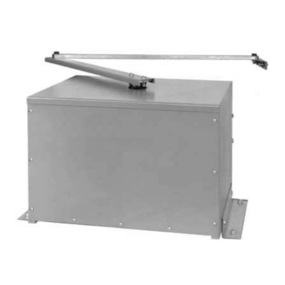
MODEL SW470
MEDIUM DUTY SWING GATE OPERATOR
2 YEAR WARRANTY
Serial # _______________________
(located on electrical box cover)
Installation Date _________________
HEAVY DUTY SWING GATE OPERATOR
INTENDED FOR PROFESSIONAL INSTALLATION ONLY.
VISIT WWW.LIFTMASTER.COM TO LOCATE A PROFESSIONAL
INSTALLING DEALER IN YOUR AREA.
THIS MANUAL IS TO BE LEFT WITH THE PROPERTY OWNER.
MODELS SW470 AND SW490 ARE FOR VEHICULAR PASSAGE GATES
ONLY AND NOT INTENDED FOR PEDESTRIAN PASSAGE GATE USE.
MODEL SW490
GL
Advertisement
Table of Contents
Troubleshooting

Subscribe to Our Youtube Channel
Related Manuals for Chamberlain LIFTMASTER PROFESSIONAL SW470


Summary of Contents for Chamberlain LIFTMASTER PROFESSIONAL SW470
- Page 1 MODEL SW470 MEDIUM DUTY SWING GATE OPERATOR 2 YEAR WARRANTY Serial # _______________________ (located on electrical box cover) Installation Date _________________ HEAVY DUTY SWING GATE OPERATOR INTENDED FOR PROFESSIONAL INSTALLATION ONLY. VISIT WWW.LIFTMASTER.COM TO LOCATE A PROFESSIONAL INSTALLING DEALER IN YOUR AREA. THIS MANUAL IS TO BE LEFT WITH THE PROPERTY OWNER.
-
Page 2: Table Of Contents
OPERATOR SPECIFICATIONS Carton Inventory ........2 Operator Dimensions and Specifications . -
Page 3: Operator Dimensions And Specifications
O P E R A T O R D I M E N S I O N S A N D S P E C I F I C A T I O N S MODEL SW470 • 1/2 HP Motor Maximum Gate Weight –... -
Page 4: Entrapment Protection Types
U L 3 2 5 M O D E L C L A S S I F I C A T I O N S The SW470 and SW490 are intended for use with vehicular swing gates. The opener can be used in Class I, Class II, Class III and Class IV applications. -
Page 5: Suggested Safety Protection Device Locations
S U G G E S T E D S A F E T Y P R O T E C T I O N D E V I C E L O C A T I O N S SWING GATE SYSTEM Telephone Entry System... -
Page 6: Safety Installation Information
S A F E T Y I N S T A L L A T I O N I N F O R M A T I O N Vehicular gate systems provide convenience and security. Gate systems are comprised of many component parts. The gate operator is only one component. -
Page 7: General Requirements
G A T E C O N S T R U C T I O N I N F O R M A T I O N Vehicular gates should be installed in accordance with ASTM F2200: Standard Specification for Automated Vehicular Gate Construction. For a copy, contact ASTM directly at 610-832-9585 or www.astm.org. -
Page 8: Safety For Swing And Ornamental Grill Type Gates
SAFETY PRECAUTIONS FOR SWING AND ORNAMENTAL "GRILL TYPE GATES" WARNING WARNING To prevent SERIOUS INJURY or DEATH from a moving gate: CAUTION • Entrapment protection devices MUST be installed to protect anyone who may come near a moving gate. • Locate entrapment protection devices to protect in BOTH the open and close gate cycles. -
Page 9: Installation
POST MOUNTING (SW470) 1. Locate and anchor two posts made of 3" (7.6 cm) outer diameter heavy walled pipe. Posts should be parallel and square to the gate. IMPORTANT NOTE: The distance between mounting posts and the relative location of the operator to the gate and fence is critical. -
Page 10: Pad Mounting (Sw470)
PAD MOUNTING (SW470) 1. Layout the concrete pad (Figure 1). IMPORTANT NOTE: The relative location of the operator to the fence and the gate is critical. Be sure that the measurements for operator mounting are taken from the centerline of the fence and of the gate hinge. -
Page 11: Pad Mounting (Sw490)
PAD MOUNTING (SW490) 1. Measure the gate length and select appropriate “P” dimension from the gate installation table. 2. Layout the concrete pad as detailed in Figure 1. IMPORTANT NOTE: The relative location of the operator to the fence and the gate is critical. Be sure that the measurements for operator mounting are taken from the centerline of the fence and of the gate hinge. -
Page 12: Control Arm And Gate Bracket Installation (Sw470)
CONTROL ARM ASSEMBLY (SW470) 1. Set the control arm stop on the operator in the positions appropriate for the installation (Figure 1). 2. Install the arm channel to the hub assembly to the operator output shaft. 3. Secure the arm channel to arm hub with 1/4-20 black plastic knobs provided (Hub is factory installed - Figure 2). -
Page 13: Control Arm Assembly (Sw490)
CONTROL ARM ASSEMBLY (SW490) 1. Set the control arm’s close stop on the operator so that its position corresponds with the handling of the installation (Figure 1). 2. Remove the open stop, as it is not to be used in this application. -
Page 14: Manual Disconnect
CONTROL ARM ASSEMBLY (SW490) continued Gate Hinge Open gate position 90º 2" 34" Closed gate stop Control arm hub assembly Control arm extension Output Shaft 13" MANUAL DISCONNECT MODEL SW470 1. Remove the (2) black knobs securing the control arm to the operator (Figure 1). -
Page 15: Wiring
To reduce the risk of SEVERE INJURY or DEATH: • ANY maintenance to the operator or in the area near the operator MUST not be performed until disconnecting the electrical power and locking-out the power via the operator power switch. Upon completion of maintenance the area MUST be cleared and secured, at that time the unit may be returned to service. -
Page 16: On/Off Switch Power Wiring
ON/OFF SWITCH POWER WIRING NOTE: Before running power wiring refer to wiring specifications on page 15 for correct wire gauges. Secure all electrical power connections inside the disconnect switch electrical box. Refer to electrical wiring diagrams on pages 31-33. IMPORTANT: On three phase operators, power connections must be properly phased. -
Page 17: Adjustment
WARNING PROGRAMMING THE RADIO RECEIVER CAUTION SET SECURITY MODE The Universal Receiver can be used with up to 15 315 MHz rolling code remote controls or PINs in HIGH security mode. Alternately, it can be used with up to 31 of any type 315 MHz remote control in NORMAL security mode, including any combination of rolling code, billion code, or dip switch remotes. -
Page 18: Limit Switch Adjustment
LIMIT SWITCH ADJUSTMENT NOTE: For limit location and configuration refer to Figure 1. 1. Before turning on power, disconnect extension arm from gate bracket so gate is no longer connected to operator. Push manual release pin(s) up through the control arm, slide clevis pin in place and secure with a cotter pin. -
Page 19: Rpm Sensor (Hall Effect) Adjustment
RPM SENSOR (HALL EFFECT) ADJUSTMENT NOTE: Normally the RPM sensor (hall effect) does not need adjustment, but may go out of alignment due to shipping vibration or rough handling. These operators use an internal entrapment protector system. This system consists of the control board, magnet, and RPM sensor. -
Page 20: Sequenced Access Management System (Sams)
SEQUENCED ACCESS MANAGEMENT SYSTEM (SAMS) The Sequenced Access Management System or SAMS allows the customer more control when managing vehicular entrances to areas such as apartment complexes, businesses and gated communities. The basic concept of the system is that traffic is controlled by two gates installed in tandem, a fast moving gate such as a barrier gate operator and a slower moving more secure or ornamental gate such as a single or pair of slide/swing gate... -
Page 21: Accessory Wiring
ACCESSORY WIRING All inputs are normally open and momentary, except the stop (N.C.). The following instructions are based upon UL325, and include recommendations for significant increase in safety. We strongly recommend that you follow the UL guidelines presented throughout the manual. Refer to instructions shipped with optional control devices for mounting, wiring, programming and adjustment. - Page 22 ACCESSORY WIRING Field Wiring Terminals 9 & 5 - Obstruction Open (Edge/Photo Eye Input) Edge Input: See Programming Section This input will reverse an opening gate to the close limit. Activating this input when the gate is closing will have no effect. NOTE: If upon reversal a second separate obstruction is detected (gate edge or RPM sensor), gate will stop and alarm.
-
Page 23: Control Board Illustration
C O N T R O L B O A R D I L L U S T R A T I O N Main Terminal Wiring J2 Connector J5 Connector SAMS Relay Drive Troubleshooting LEDs J1 Terminal Troubleshooting LEDs J4 Connector Master/Second Dip Switch #4... -
Page 24: Control Board Programming And Features
CONTROL BOARD PROGRAMMING AND FEATURES MOTOR LEARN FUNCTION (FORCE PROFILE) This function is preprogrammed at factory. If either board or motor is replaced, the controller will need to be programmed to “LEARN” the specific motor RPM profile of your operator. Switch “S3”... -
Page 25: Troubleshooting Leds
CONTROL BOARD PROGRAMMING AND FEATURES (CONTINUED) RELAY DRIVE TROUBLESHOOTING LEDS There are 5 troubleshooting LEDs on relay drives K1 through K5. These LEDs will be illuminated when the microcontroller relay drive is activated. LED NAME Contactor A Contactor B Lock Alarm TROUBLESHOOTING LEDS There are 9 troubleshooting LEDs. -
Page 26: Program Settings
PROGRAM SETTINGS (DIP SWITCH S1) NOTE: For all S1, S2 and S4 switch settings to take effect, the Save Mode switch must be set to the off position. TIMER-TO-CLOSE ENABLE This switch enables the auto close timer. The timer to close feature works in conjunction with the potentiometer located on the board. - Page 27 PROGRAM SETTINGS (DIP SWITCH S2) EDGE/PHOTO OPEN This switch (S2-3) selects edge or photo sensor for the gate opening protection input. Open Photo Eye (Pause): When the controller is configured for photo eyes, the input functions to pause the gate during the opening cycle.
-
Page 28: Troubleshooting
SYMPTOM POSSIBLE CAUSES Operator fails to No Stop Control. run. Fault in the operator. Check the yellow diagnostic LED at the top right of the control board next to the programming dip switches. An accessory is active or malfunctioning. Check the red input status LEDs, D11-D31. - Page 29 T R O U B L E S H O O T I N G c o n t i n u e d SYMPTOM POSSIBLE CAUSES Master or Second Failure to cycle power after setup. operator is not functioning properly.
-
Page 30: Important Safety Instructions
IMPORTANT SAFETY INSTRUCTIONS To reduce the risk of SEVERE INJURY or DEATH: 1. READ AND FOLLOW ALL INSTRUCTIONS. 2. NEVER let children operate or play with gate controls. Keep the remote control away from children. 3. ALWAYS keep people and objects away from the gate. NO ONE SHOULD CROSS THE PATH OF THE MOVING GATE. -
Page 31: Single Phase Wiring Diagram (Sw470)
S I N G L E P H A S E W I R I N G D I A G R A M ( S W 4 7 0 ) 1 PHASE POWER IN GROUND GL CONTROL BOARD J2 PLUG 24 Vac - IN 24 Vac - COMMON SOFT OPEN... -
Page 32: Single Phase Wiring Diagram (Sw490)
S I N G L E P H A S E W I R I N G D I A G R A M ( S W 4 9 0 ) 1 PHASE POWER IN (GN) (GN) GROUND GL CONTROL BOARD J2 PLUG (GY) 24 Vac - IN... -
Page 33: Three Phase Wiring Diagram (Sw490)
T H R E E P H A S E W I R I N G D I A G R A M ( S W 4 9 0 ) ON/OFF SWITCH 3 PHASE POWER IN GL CONTROL BOARD J2 PLUG 24 Vac - IN 24 Vac -COMMON SOFT OPEN... -
Page 34: Control Connection Diagrams
C O N T R O L C O N N E C T I O N D I A G R A M S GL BOARD 24 Vac ACCESSORY POWER MAY BE FOUND ON THESE TERMINALS 24 Vac NOTE: See wiring diagrams shipped with kit for additional information. -
Page 35: Repair Parts And Illustrated Parts - Sw470
Refer to the parts lists below for replacement parts available for your operator. If optional modifications and/or accessories are included with your operator, certain components may be added or removed from these lists. Individual components of each kit may Complete Electrical Panel Replacement Kits To order a complete electrical box replacement kit, add a K- prefix to the model number of your operator. - Page 36 I L L U S T R A T E D P A R T S - S W 4 7 0...
-
Page 37: Repair Parts And Illustrated Parts - Sw490
Refer to the parts lists below for replacement parts available for your operator. If optional modifications and/or accessories are included with your operator, certain components may be added or removed from these lists. Individual components of each kit may not be available. Please consult a parts and service representative regarding availability of individual components. - Page 38 I L L U S T R A T E D P A R T S - S W 4 9 0...
-
Page 39: Variable Parts - Sw490
PART PART NO. 20-1050-1T 20-1075-1T 20-XXXX 20-1100B-2T (Motor) 20-3050-1T 20-3075B-4T 20-3100B-4T 23-XXXX 23-3001 (Switch) 23-3005 24-XXX-X 24-115-1 (Relay) 24-230-5 25-2006 25-20XX 25-2008 (Overload) 25-2010 25-2015 25-2020 25-40XX 25-4001-8K (Overload) 25-4002-5K 25-4004-K S A F E T Y A C C E S S O R I E S F O R S E C O N D A R Y E N T R A P M E N T P R O T E C T I O N The following devices are acceptable for Safety Accessories for secondary entrapment protection. -
Page 40: How To Order Repair Parts
TWO YEAR LIMITED WARRANTY The Chamberlain Group, Inc. warrants to the final purchaser of this product, for the structure in which this product is originally installed, that it is free from defect in materials and/or workmanship for a period of two years from the date of purchase. The proper operation of this product is dependent on your compliance with the instructions regarding installation, operation, maintenance and testing.
Need help?
Do you have a question about the LIFTMASTER PROFESSIONAL SW470 and is the answer not in the manual?
Questions and answers