Table of Contents
Advertisement
Quick Links
DSW-100
Specifications
Voltages:
DSW-100 & DSW-200 . . . . . . . . . . . . . . . 120/277VAC, 50/60Hz
Load Limits for each relay:
@120VAC. . . . . . . . . . . . . . 0-800W tungsten or ballast, 1/6 HP
@277VAC. . . . . . . . . . . . . . . . . . . . . . . . . . . . . 0-1200W ballast
Load Type Compatibility:
Incandescent, fluorescent, magnetic or electronic ballast
Horsepower Rating (each relay) . . . . . . . . . 1/6 HP @120VAC
Time Delay Adjustment . . . . . . . . . . . . . . . . . . . .5 to 30 minutes
Walk-Through Mode. . 3 minutes if no activity after 30 sec.
Test Mode. . . . . . 5 sec. for 10 min. with DIP switch setting
PIR Adjustment . . . . . . . . . . . . . . . . . . .High or Low (DIP switch)
Ultrasonic Adjustment . . . Minimum to Maximum (trimpot), Off
Frequency . . . . . . . . . . . . . . . . . . . . . . . . . . . . . . . . . . . . 40kHz
Light Level Adjustment . . . . . . . . . . . . . . . . . . . . . . 8fc to 180+fc
Alerts
. . . . . . . . . . . . . . . . . . . . . . . . . . . . . . Selectable Audible
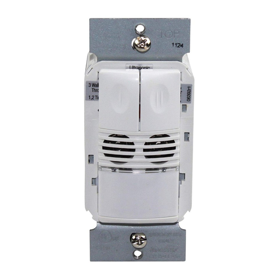
Dual Technology Wall Switch
Occupancy Sensors
DSW-100/DSW-200
DSW-200
US Patents: 5640113, 6617560
Santa Clara, CA 95050
800.879.8585
v3
Advertisement
Table of Contents

Related Manuals for Watt Stopper DSW-100


Summary of Contents for Watt Stopper DSW-100
- Page 1 Specifications Voltages: DSW-100 & DSW-200 ....120/277VAC, 50/60Hz Load Limits for each relay: @120VAC....0-800W tungsten or ballast, 1/6 HP @277VAC.
-
Page 2: Unit Description And Operation
“walk-through” mode can turn lights off after only 3 minutes, if no activity is detected after 30 seconds following an occupancy detection. The DSW-100 has one relay and one ON/OFF button. The DSW-200 contains two relays and two ON/OFF buttons to allow control of one or two loads independently. -
Page 3: Time Delays
Time Delays The DSW sensor holds the load ON until no motion is detected for the selected time delay. Select the time delay using DIP switch settings. In the DSW-200, both relays use the same delay. Test/20 min A Test Mode with a short time delay of five seconds is set when DIP switches 1 &... -
Page 4: Trigger Mode
Trigger Mode The DSW sensor has four occupancy trigger options, set with DIP switches 5 and 6. Determine the appropriate option using the Trigger matrix. In the Trigger Mode DIP switch setting table, in order to deem the area occupied: • Both requires motion detection by the PIR and the Ultrasonic. -
Page 5: Installation
ON. 5. Test and adjust the sensor if necessary. Neutral 6. Attach the cover plate. Load Line Black Neutral White Ground Green DSW-100 Wiring Neutral White White Neutral Line 1 Black Primary Load Primary... -
Page 6: Dip Switch Settings
DIP Switches Tabs Ultrasonic Cones Detection LEDs Button Red = PIR Hinges Green = Ultrasonic DSW-200 shown. DSW-100 has a PIR Lens single button and the Ultrasonic sensitivity adjustment trimpot is in a slightly different position. Call 800.879.8585 for Technical Support... -
Page 7: Sensor Adjustment
ADJUSTMENTS Sensor Adjustment Remove the wall plate. Remove the button cap by firmly squeezing together the top sides of the button assembly. Gently pull it away from the unit. When the adjustments are completed, replace the button cap by inserting its hinges into the tabs on the main unit and then squeeze the top of the button while pressing it into the unit. -
Page 8: Cover Plates
Lights do not turn OFF 1. There can be up to a 30 minute time delay after the last motion is detected. To verify proper operation, set DIP switch 1 to ON, then reset switches 1 and 2 to OFF to start Test Mode. Move out of view of the sensor.
Need help?
Do you have a question about the DSW-100 and is the answer not in the manual?
Questions and answers