Table of Contents
Advertisement
Quick Links
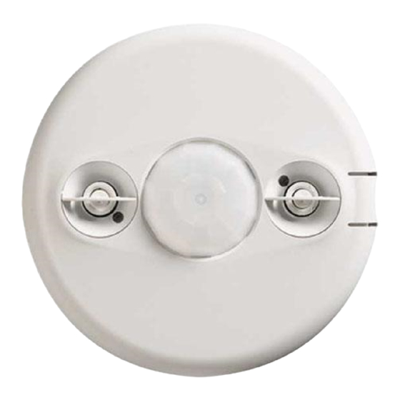
360° Dual Technology • Low Voltage
Specifications
Voltage ........................ 18-28VDC/VAC, half wave rectified AC
Current Consumption ..................................................... 25 mA
Power Supply ..................................WattStopper Power Packs
Operating Temperature ..................... 32° to 131°F (0° to 55°C)
Time Delay Adjustment ....................30 seconds to 30 minutes
Walk-Through Mode ...3 minutes if no activity after 30 sec.
Test Mode ............................... 5 sec. upon DIP switch reset
PIR Coverage (Typical) .................................................. 1300 ft
Sensitivity Adjustment ..........High or Low (DIP switch setting)
Ultrasonic Coverage (Typical) ....................................... 1300 ft
Sensitivity Adjustment ..... Minimum to Maximum (trimpot)
Frequency .................................................................. 40kHz
UL & CUL Listed for use with WattStopper Power Packs
DT-305
Occupancy Sensor
with Manual On feature
U.S. Patent: 7,277,012
Santa Clara, CA 95050
v3
2
2
Advertisement
Table of Contents

Subscribe to Our Youtube Channel
Related Manuals for Watt Stopper DT-305


Summary of Contents for Watt Stopper DT-305
- Page 1 DT-305 360° Dual Technology • Low Voltage Occupancy Sensor with Manual On feature Specifications Voltage ......18-28VDC/VAC, half wave rectified AC Current Consumption ............. 25 mA Power Supply ........WattStopper Power Packs Operating Temperature ..... 32° to 131°F (0° to 55°C) Time Delay Adjustment ....30 seconds to 30 minutes...
-
Page 2: Unit Description
The DT-305 turns lighting systems on and off based on occupancy. The DT-305 provides numerous operating modes that can be combined to create the ideal custom control. The sensors can be configured to turn lighting on, and hold it on as long as either or both technologies detect occupancy. -
Page 3: Placement Guidelines
It is also recommended to place the sensor at least 4 to 6 feet away from air supply vents. Mount the sensor to the ceiling. The DT-305 is designed for a ceiling heights of about 8-12 feet. Mounting above or below this range will significantly affect the coverage patterns. - Page 4 Sensor If the space is larger than 30’ x 30’ it will be necessary to use more than one sensor to ensure complete coverage. Coverage 36 ft (10.97m) Ultrasonic Overlap Ultrasonic Coverage 36 ft (10.97m) Sensor Ultrasonic Overlap Call 800.879.8585 for Technical Support...
-
Page 5: Wiring Directions
TURN POWER OFF AT THE CIRCUIT BREAKER BEFORE INSTALLING POWER PACKS, SWITCHES OR SENSORS. Each WattStopper BZ series power pack can supply power for 5 DT-305 sensors. When using more sensors than this, multiple power packs are required. Refer to the wiring diagram on... -
Page 6: Connecting Wires
Low Voltage Load #2 Class 2 (Optional) Line Black Voltage Common Blue Control Out +24V Ceiling Depluggable Terminal Spring Clips (2) Rear Housing Line Voltage Switches Front Cover DT-305 Standard wiring with local off switch Call 800.879.8585 for Technical Support... - Page 7 Jumper Man.Switch Back LVS-1 Ceiling Depluggable Terminal Spring Clips (2) LVS-1 Rear Housing For low voltage momentary switch use trigger option Front Cover 6 or 7 DT-305 Manual-On wiring with low voltage momentary switch Visit our website for FAQs: www.wattstopper.com...
-
Page 8: Mounting The Sensor
MOUNTING THE SENSOR Directly to Ceiling 1. Attach the plastic spring clips to the edge of the sensor in the slots provided. Ceiling 2. Cut a 3.5” to 4” round hole in the acoustic ceiling tile at the mounting Depluggable terminal location. -
Page 9: Sensor Adjustment
SENSOR ADJUSTMENT This unit is pre-set for basic operation as described in this guide. Adjustment is optional. The sensors are factory preset to allow for quick installation in most applications. Verification of proper wiring or coverage, or customizing the sensor’s settings can be done using the following procedures. - Page 10 Option 1 OCCUPANCY LOGIC: SWITCHES: 6, 7, 8 Option 2 Option 3 The DT-305 has 8 logic configurations for occupancy Option 4 triggers, set with DIP switches 6, 7 & 8. Determine the Option 5 appropriate Occupancy Logic Option using the Trigger Option 6 matrix, then set the DIP switches accordingly.
-
Page 11: Overload Protection
MANUAL ON FUNCTION The Manual ON function is facilitated by installing a momentary switch such as the WattStopper LVS-1 Momentary Toggle Switch, or RS2-3 Low Voltage Momentary Switch. This switch connects to the sensor’s Manual (Man.) Switch and +24V terminals as shown in the wiring diagram. Each time the switch is pressed, the load changes state. -
Page 12: Troubleshooting
TROUBLESHOOTING CAUTION TURN POWER OFF AT THE CIRCUIT BREAKER BEFORE WORKING WITH OR NEAR HIGH VOLTAGE. For any unexpected operation 1. Check DIP switch settings. 2. Make sure the switches are set according to the defined settings in the DIP Switch setting chart. - Page 13 Red and Green LEDs flash 1. Check all sensor and power pack connections. 2. Check for 24VDC at the power pack blue and black wire connections to sensor while sensor is active. • If there is no voltage, replace the sensor. • If there is voltage, check for 24VDC between the blue and black wire at the power pack. If 24VDC is present and the relay is not closing, replace it. • If 24VDC is not present, check for a break in the low voltage wiring.
-
Page 14: Ordering Information
Auxiliary Relay Pack: 120/277VAC, 60Hz, 20A Ballast 347VAC, 60Hz, 15A Ballast All sensors are white. BZ series power packs supply power for up to 5 DT-305 sensors. WARRANTY INFORMATION WattStopper warranties its products to be free of defects in materials and workmanship for a period of five (5) years.
Need help?
Do you have a question about the DT-305 and is the answer not in the manual?
Questions and answers