Table of Contents
Advertisement
Quick Links
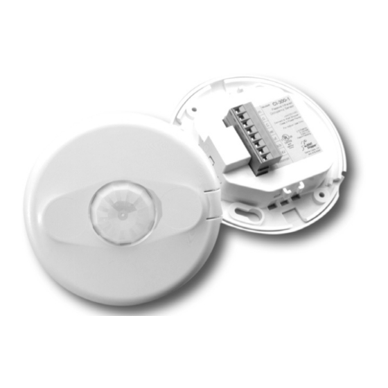
360° Passive Infrared • Low Voltage
with Light Level, Isolated Relay and Manual On feature
Specifications
Voltage ........................ 18-28VDC/VAC, half wave rectified AC
Current Consumption ..................................................... 15 mA
Power Supply ..................................WattStopper Power Packs
Isolated Relay Rating ...................................... 1A @30VDC/VAC
Operating Temperature ..................... 32° to 131°F (0° to 55°C)
Light Level One-Step Adjustment ....................... 10FC—300FC
Time Delay Adjustment ....................30 seconds to 30 minutes
Walk-Through Mode ...3 minutes if no activity after 30 sec.
Test Mode ............................... 5 sec. upon DIP switch reset
PIR Coverage
Model CI-300 ................................................... up to 1200ft 2
Model CI-300-1 ................................................. up to 500ft 2
Sensitivity Adjustment ................. High or Low (DIP switch)
UL & CUL Listed for use with WattStopper Power Packs
CI-300
Occupancy Sensor
Santa Clara, CA 95050
v3
Advertisement
Table of Contents

Related Manuals for Watt Stopper CI-300


Summary of Contents for Watt Stopper CI-300
- Page 1 Walk-Through Mode ...3 minutes if no activity after 30 sec. Test Mode ....... 5 sec. upon DIP switch reset PIR Coverage Model CI-300 ........... up to 1200ft 2 Model CI-300-1 ..........up to 500ft 2 Sensitivity Adjustment ....High or Low (DIP switch) UL &...
-
Page 2: Unit Description
The CI-300 provides a 360° coverage pattern. Two lens patterns are available. The CI-300 provides up to 1200 square feet of coverage and the CI-300-1 provides up to 500 square feet of coverage. The coverage shown represents walking motion at a mounting height of 8 feet. -
Page 3: Placement Guidelines
4 to 6 feet away from air supply ducts as rapid air currents or the differences in temperatures may cause false activations. Mount the sensor to the ceiling. The CI-300 sensors are designed for a ceiling height of about 8-10 feet. Mounting above or below this range will significantly affect the coverage patterns. -
Page 4: Wiring Directions
TURN POWER OFF AT THE CIRCUIT BREAKER BEFORE INSTALLING POWER PACKS OR SENSORS. Each WattStopper BZ series power pack can supply power for 8 CI-300 sensors. When using more sensors than this, multiple power packs are required. Refer to the wiring diagram on the next... -
Page 5: Connecting Wires
White Load #1 Power Pack Low Voltage Load #2 Class 2 (Optional) Line Black Voltage Common Blue Control Out +24V Ceiling Depluggable Terminal Spring Clips (2) Rear Housing Line Voltage Switches Front Cover CI-300 Visit our website for FAQs: www.wattstopper.com... - Page 6 Class 2 +24V Blue +24V Black Man.Switch Control Out Jumper Common Back Man.Switch LVS-1 Ceiling Depluggable Terminal Spring Clips (2) LVS-1 Rear Housing For low voltage momentary switch set Front Cover DIP switches #7 ON CI-300 Call 800.879.8585 for Technical Support...
-
Page 7: Mounting The Sensor
MOUNTING THE SENSOR Directly to Ceiling 1. Attach the plastic spring clips to the edge of the sensor in the slots Ceiling provided. 2. Cut a 3.5” to 4” round hole in the acoustic ceiling tile at the Depluggable terminal mounting location. -
Page 8: Sensor Adjustment
SENSOR ADJUSTMENT This unit is pre-set for basic operation as described in this guide. Adjustment is optional. The sensors are factory preset to allow for quick installation in most applications. Verification of proper wiring or coverage, Keyhole slots Light level or customizing the (for mounting to pushbutton... - Page 9 LIGHT LEVEL FEATURE The Light Level feature holds lights off upon initial occupancy if adequate ambient light exists. It will not turn the lights off if they are on. The default setting is for maximum, meaning that even the brightest ambient light will not hold the lights off.
- Page 10 5. When the LED stop flashing, replace the Front Cover *Disabling Light Level Pressing the pushbutton for 5 seconds or more resets the light to default (maxi- mum). Press and hold the Light Level button for 5 seconds or until the detection LED turns ON and then OFF.
-
Page 11: Dip Switch Setting
On Mode: Switch 7 The Manual ON function is facilitated by installing a momentary switch such as a Watt Stopper LVS-1 Momentary Toggle Switch, or RS2-3 Low Voltage Momentary Switch. This switch connects to the sensor’s Manual (Man.) Switch and +24V terminals as shown in the wiring diagram. Each time the switch is pressed, the load changes state. -
Page 12: Overload Protection
Manual On: In this mode, the switch is required to turn on the load. The sensor is then used to keep the load on, based on occupant activity. After the time delay ends, if there is no movement detected within the 30 second re-trigger period the manual switch must be used to turn ON the load. -
Page 13: Troubleshooting
TROUBLESHOOTING CAUTION TURN POWER OFF AT THE CIRCUIT BREAKER BEFORE WORKING WITH OR NEAR HIGH VOLTAGE. Lights do not turn ON with occupancy, and the following condition exists: • Red LED does not flash: 1. Check that the circuit breaker has been turned back on. 2. - Page 14 3. Disconnect power pack’s blue wire: If the lights do not turn off, replace power pack. Reconnect blue wire. If the lights turn off, the problem may be in the sensor. To check: • Reconnect the blue wire. • Turn sensitivity and time delay to minimum and allow the sensor to time out. • If the lights turn off, the sensor is working properly (see number 1, above, and “Sensor Adjustment”...
-
Page 15: Ordering Information
BZ-150 Power Pack: 120/277VAC, 50/60Hz, 225mA, 20A bal- last or incandescent, 1HP@120/250VAC S120/277/347E-P Auxiliary Relay Pack: 120/277VAC, 60Hz, 20A Ballast, 347VAC, 60Hz, 15A Ballast All sensors are white. BZ series power packs supply power for up to 8 CI-300 sensors. -
Page 16: Warranty Information
WARRANTY INFORMATION WattStopper warranties its products to be free of defects in materials and workmanship for a period of five (5) years. There are no obligations or liabilities on the part of WattStopper for consequential damages arising out of or in connection with the use or performance of this product or other indirect damages with respect to loss of property, revenue, or profit, or cost of removal, installation or reinstallation.
Need help?
Do you have a question about the CI-300 and is the answer not in the manual?
Questions and answers