Table of Contents
Advertisement
Quick Links
with Light Level, Isolated Relay and Manual On features
SPECIFICATIONS
Voltage ............................................................................. 18-28VDC/VAC
Current Consumption ..................................................................... 25mA
Power Supply .................................................WattStopper Power Packs
Isolated Relay Rating ..................................................... 1A @30VDC/VAC
Operating Temperature ................................... 32° to 131°F (0° to 55°C)
Light Level One-Step Adjustment ...................................10FC to 200FC)
Time Delay Adjustment ................................... 30 seconds to 30 minutes
Walk-Through Mode ..................3 minutes if no activity after 30 sec.
Test Mode ...................................................5 sec. or DIP switch reset
PIR Coverage (Typical) ................................................................ 1000 ft2
Sensitivity Adjustment ....................High or Low (DIP switch setting)
Ultrasonic Coverage (Typical) .............................................. 800-1200 ft2
Sensitivity Adjustment .................... Minimum to Maximum (trimpot)
Frequency ................................................................................. 40kHz
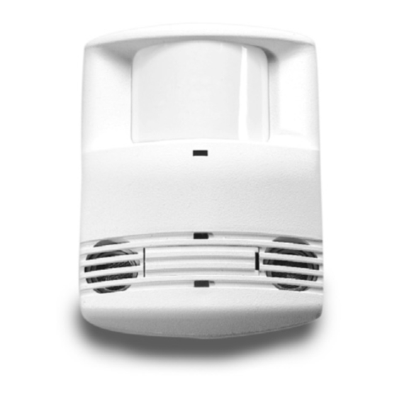
Dual Technology • Low Voltage
DT-200
Occupancy Sensor
Santa Clara, CA 95050
version 3
Advertisement
Table of Contents

Related Manuals for Watt Stopper DT-200


Summary of Contents for Watt Stopper DT-200
-
Page 1: Specifications
DT-200 version 3 Dual Technology • Low Voltage Occupancy Sensor with Light Level, Isolated Relay and Manual On features SPECIFICATIONS Voltage ................18-28VDC/VAC Current Consumption ..............25mA Power Supply ..........WattStopper Power Packs Isolated Relay Rating ............. 1A @30VDC/VAC Operating Temperature ........32° to 131°F (0° to 55°C) Light Level One-Step Adjustment ........10FC to 200FC) -
Page 2: Unit Description
The DT-200 turns lighting systems on and off based on occupancy and ambient light levels. The DT-200 offers numerous operating modes that can be combined to create the ideal custom control. -
Page 3: Placement Guidelines
4 to 6 feet away from air supply ducts. The DT-200 is designed for a ceiling height of about 8-10 feet. Mounting above or below this range will significantly affect the coverage patterns. As a general rule, each occupant should be able to clearly view the sensor. -
Page 4: Wiring Directions
TURN POWER OFF AT THE CIRCUIT BREAKER BEFORE INSTALLING POWER PACKS OR SENSORS. Each WattStopper BZ series power pack can supply power for 3 DT-200 sensors. When using more sensors than this, multiple power packs are required. Refer to the wiring diagram on the next page for the following procedures: Connect the LOW VOLTAGE: • RED wire (+24VDC) from power pack to the red wire on the sensor. - Page 5 Line Feed Through Neutral Load #1 Power Pack Low Voltage Class 2 Load #2 (Optional) Line Black Voltage Black (Common) Blue Blue (Control Out) Red (+24V) Grey (Man Switch) Ceiling Line Voltage Switches DT-200v3 Grey wire on sensor is only used when Occupancy connecting a manual momentary switch.
-
Page 6: Mounting The Sensor
MOUNTING THE SENSOR The DT-200 sensors can be mounted to walls or ceilings with the supplied swivel bracket, and the supplied Half-Circle junction box cover plate if Notch necessary (see figure B). Mounting at fixture height is most effective. Ceiling: It is best to leave... - Page 7 Sensor Angle Adjustment While watching the LEDs for flashes (Red LED indicates activation from the PIR sensor; Green LED indicates activation from the ultrasonic sensor), have a person walk back and forth at the far end of the space. Increase or decrease mounting angle as needed until the desired coverage is achieved.
- Page 8 LIGHT LEVEL FEATURE The Light Level feature holds lights off upon initial occupancy if adequate ambient light exists. It will not turn the lights off if they are on. The default setting is for maximum, meaning that even the brightest ambient light will not hold the lights off.
- Page 9 *Disabling Light Level Pressing the pushbutton for 5 seconds or more resets the light to default (maximum). Press and hold the Light Level button for 5 seconds or until the detection LEDs turn ON and then OFF. The LEDs flash rapidly for 10 seconds after the setting has changed.
-
Page 10: Sensor Adjustment
SENSOR ADJUSTMENT The sensors are factory preset to allow for quick installation in most applications. Verification of proper wiring or coverage, or customizing the sensor’s settings can be done using the following procedures. To make adjustments, open the Front Cover with a small screwdriver. -
Page 11: Dip Switch Setting
• Minimum forces a reduced detection range for Minimum the PIR. Maximum • Maximum causes the DT-200 to monitor the controlled environment and automatically select the maximum sensitivity that will provide reliable operation without false detection. This setting is 6 7 8 Settings constantly updated. -
Page 12: Overload Protection
MANUAL ON FUNCTION The Manual ON function is facilitated by installing a momentary switch such as Watt Stopper LVSW Momentary Toggle Switch. The switch connects to the sensor’s Manual (Man.) Switch and +24VDC terminals as shown in the wiring diagram. Each time the switch is pressed, the load changes state. -
Page 13: Troubleshooting
TROUBLESHOOTING CAUTION TURN POWER OFF AT THE CIRCUIT BREAKER BEFORE WORKING WITH OR NEAR HIGH VOLTAGE. For any unexpected operation 1. Check DIP switch settings. 2. Make sure the switches are set according to the defined settings in the DIP Switch Setting chart. - Page 14 Red and Green LEDs flash 1. Check all sensor and power pack connections. 2. Check if Light Level is enabled. • If occupancy indicator LEDs blink together every few seconds, sensor is using Light Level feature. • If Light Level functionality is not desired, press and hold for 5 seconds to return sensor to the default setting (maximum).
- Page 15 3. Reconnect the blue wire. • Turn sensitivity and time delay to minimum, and allow the sensor to time out. • If lights turn off, the sensor is working properly – adjust sensitivity and time delay for the sensor. • If lights do not turn off, check the wiring between the sensor and power pack.
-
Page 16: Ordering Information
ORDERING INFORMATION Catalog # Description DT-200 Dual Technology Occupancy Sensor, Low Voltage w/Isolated Relay DT-205 Dual Technology Occupancy Sensor, Low Voltage BZ-50, 150 Power Pack: 120/277VAC, 50/60Hz, 225mA with relay connected, 20A ballast/incandescent B347D-P Power Pack: 347VAC, 60Hz, 150mA. 15A ballast...
Need help?
Do you have a question about the DT-200 and is the answer not in the manual?
Questions and answers