
Subscribe to Our Youtube Channel
Related Manuals for Roger PRT32


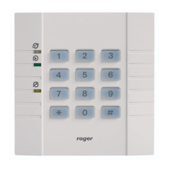
Summary of Contents for Roger PRT32
- Page 1 PRT32 v1.0 RFID/PIN Access Reader Firmware v74.7 I n s t a l l a t i o n a n d P r o g r a m m i n g G u i d e...
-
Page 2: Table Of Contents
PRT32 v1.0 fv74.7 Rev. A EN 7/3/2009 _________________________________________________________________________________________ 1. Table of contents Table of contents ................2 Important note – read this first ............3 Glossary and terms ................3 General ....................4 ... -
Page 3: Important Note - Read This First
MASTER or INSTALLER. Whenever required (e.g. when stolen or lost) installer may program new MASTER and INSTALLER cards into a unit. The factory new PRT32 reader is shipped with MASTER and INSTALLER users not programmed. -
Page 4: General
Offline mode) or for use with an external access control unit (ACU) supporting compatible data interface formats (Online mode). The PRT32 configured for Online mode works as a slave unit serving a sole purpose of reading cards and/or entering a PIN codes then providing subsequent transmission of such collected data to the host ACU for further processing. -
Page 5: Features
• Online mode • Offline mode 5.1. Online mode (host-controlled operation) When in this mode, PRT32 reads cards or PINs and then transmits the collected data to the host unit for further processing. The PRT32 offers the following data transmission formats: •... -
Page 6: Wiegand Format
CLK and DTA lines. Depending on the selected version of the transmission format, the PRT32 uses 26, 34, 42 or 66 bits to transmit a data to the host unit. Card code is always transmitted as a whole... -
Page 7: Racs Format
[#] key, which is treated as the end of a PIN code. In RACS format when IN1 is triggered, the PRT32 will stop reading cards and PINs till the moment when IN1 will be released. -
Page 8: Simple Stand-Alone Mode
PRT32 v1.0 fv74.7 Rev. A EN 7/3/2009 _________________________________________________________________________________________ The maximum length of the cable run between a PRT reader and an XM-2 module and optional secondary PRT reader is limited to 150 m. For two-way door control the primary PRT unit needs to be configured for Full Stand-alone mode while the second (slave) reader needs to be configured for RACS Online mode with address set to ID=0. -
Page 9: Managing The Users
PIN code to be deleted, otherwise the only one method to remove it from the memory will be full Memory Reset. 6.3. User identification In PRT32 user can be identified by card, PIN or both (card and PIN). The method Page 9 of 29... -
Page 10: Armed And Disarmed Modes
(light control, heating control etc). Note: Upon powering on, the PRT32 automatically returns to the arming mode (Armed or Disarmed) it was in before powered off. Also, the reader returns to its original Armed/Disarmed state after leaving the programming mode. -
Page 11: Examples
PRT32 v1.0 fv74.7 Rev. A EN 7/3/2009 _________________________________________________________________________________________ action needed by a TOGGLE user to rearm the reader is to read twice the TOGGLE card or to enter twice the TOGGLE PIN code — however, when the reader operates with the Card and PIN mode, user needs to do both things, read a card and enter a PIN code. -
Page 12: Operation With Xm-2 I/O Extension Module
Armed mode in order to disable unlocking of a door. 6.7. Operation with XM-2 I/O extension module In Full stand-alone mode the PRT32 requires connection to an external XM-2 I/O extension module. Each input and output of the XM-2 can be programmed on the same basis as internal inputs and outputs of a reader. -
Page 13: Door Bell Function
The indication of a door bell is accompanied by continuous sound generated by the internal buzzer. Note: In PRT32 the long press of [#] key is treated as Door Bell button while the use of [#] key which follows digits of a PIN code is used to mark the end of a PIN code. -
Page 14: Programming
7. Programming The programming steps which are required for PRT32 reader depends on the operating mode to which it was configured for. The PRT32 can not be programmed from PC, it can be only programmed manually from its keypad. Note: The programming of a reader can be done on primary reader only. - Page 15 PRT32 v1.0 fv74.7 Rev. A EN 7/3/2009 _________________________________________________________________________________________ Online mode, RACS communication interface, address ID=2 Online mode, RACS communication interface, address ID=3. Online mode, The reader operates as a slave reader connected to a Magstripe communication host controller that requires Magstripe data transmission interface format.
-
Page 16: Memory Reset - Programming Master And Installer Users
PRT32 v1.0 fv74.7 Rev. A EN 7/3/2009 _________________________________________________________________________________________ Each key pressed is immediately transmitted to the host controller as Each key pressed is a sequence of 4 bits (XXXX) which represent the code of the pressed transmitted separately, key, no control bits added. This format is compatible with HID 5355 no control bits added series readers, option: Without Parity. -
Page 17: Installer Programming Mode
• Option: Access disabled when reader armed, option OFF 7.5. Installer Programming mode Use this mode to configure various functionalities of the PRT32 reader. You can enter it by presenting your INSTALLER card to the unit or entering the INSTALER PIN code. - Page 18 PRT32 v1.0 fv74.7 Rev. A EN 7/3/2009 _________________________________________________________________________________________ Function settings for the REL1 output on the XM-2 module (when in Full stand- alone mode) or for the CLK line (when in Simple stand-alone mode): [0] – Line off, line is disabled [1] –...
-
Page 19: User Programming Mode
PRT32 v1.0 fv74.7 Rev. A EN 7/3/2009 _________________________________________________________________________________________ Note: Depending of the selected reader operating mode (either Full stand-alone or Simple stand-alone) the parameters C5 and C6 may refer to REL1 and REL2 output lines on remote XM-2 I/O extension module or to CLK and DTA lines located on a reader. -
Page 20: User Programming Commands
PRT32 v1.0 fv74.7 Rev. A EN 7/3/2009 _________________________________________________________________________________________ 7 . 6 . 1 . U s e r p r o g r a m m i n g c o m m a n d s Note: Any attempt to program an already registered card or PIN will be indicated as a programming error. -
Page 21: Programming Examples
PRT32 v1.0 fv74.7 Rev. A EN 7/3/2009 _________________________________________________________________________________________ [*][6][ID][PIN][#][Card] – Add single TOGGLE LTD user with an ID, PIN and card The new TOGGLE LTD user is registered in the memory at the location indicated by ID number (ID=000–119). Both the entered PIN and the presented proximity card are assigned to him. -
Page 22: Acoustic And Optical Signals In Offline Mode
PRT32 v1.0 fv74.7 Rev. A EN 7/3/2009 _________________________________________________________________________________________ Example 2: Delete a user with ID=45 - programming sequence: [9][0][4][5][#] • Read your MASTER card • The reader enters User Programming mode (LED OPEN is on and its LED STATUS is on and red) •... -
Page 23: Installation Guidelines
PRT32 v1.0 fv74.7 Rev. A EN 7/3/2009 _________________________________________________________________________________________ The reader is in Installer Programming mode. Green Green — Waiting for the user to enter the next part of the command or Orange — — Flashing programming function. Orange, A user identifier (Card/PIN) has been entered. -
Page 24: Appendix
PRT32 v1.0 fv74.7 Rev. A EN 7/3/2009 _________________________________________________________________________________________ Appendix Connection Terminals Offline mode Connection Online mode terminal Simple Stand-alone Full Stand-alone (unit connected to host ACU) mode mode +12V Supply input plus. Supply input minus. Can be configured as CLOCK DATA 0 line for Wiegand formats an input or output. - Page 25 PRT32 v1.0 fv74.7 Rev. A EN 7/3/2009 _________________________________________________________________________________________ Ordering Codes RFID/PIN reader, grey color. PRT32 Relay module, the RM-2 offers two relays with one NO/NC contact 1.5A/24V rated, relay RM-2 contacts are protected by over-voltage components. Module is delivered with plastic box.
- Page 26 PRT32 v1.0 fv74.7 Rev. A EN 7/3/2009 _________________________________________________________________________________________ Table: List of users Site name: Reader location: ID Number Card number Type User Name Master Installer Page 26 of 29...
- Page 27 PRT32 v1.0 fv74.7 Rev. A EN 7/3/2009 _________________________________________________________________________________________ Page 27 of 29...
- Page 28 PRT32 v1.0 fv74.7 Rev. A EN 7/3/2009 _________________________________________________________________________________________ Page 28 of 29...
- Page 29 PRT32 v1.0 fv74.7 Rev. A EN 7/3/2009 _________________________________________________________________________________________ Page 29 of 29...
Need help?
Do you have a question about the PRT32 and is the answer not in the manual?
Questions and answers